 |
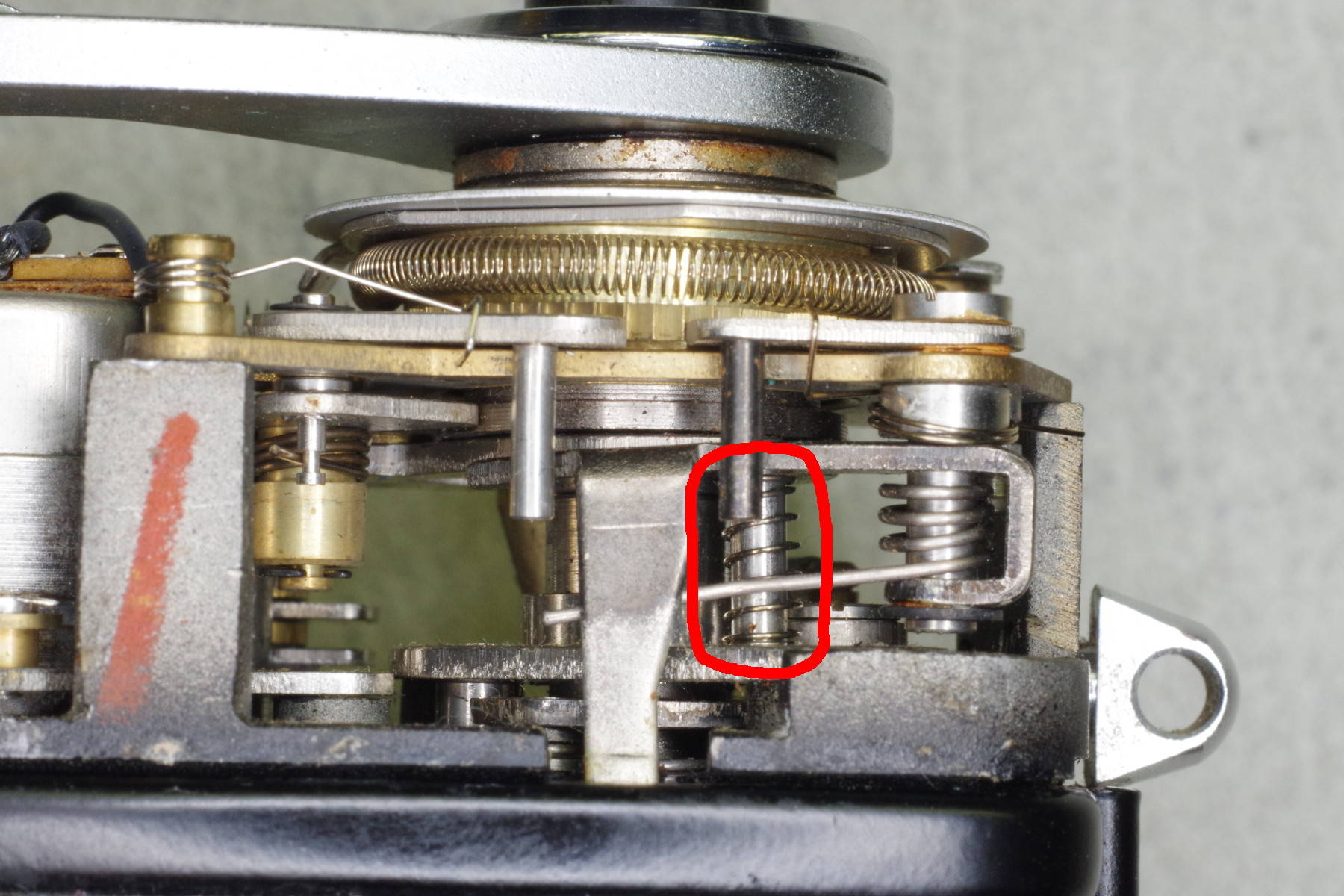
The spring circled in red provides sufficient return-force for the shutter button.
Two other springs are only used for automatic mode, so you will remove them.
|
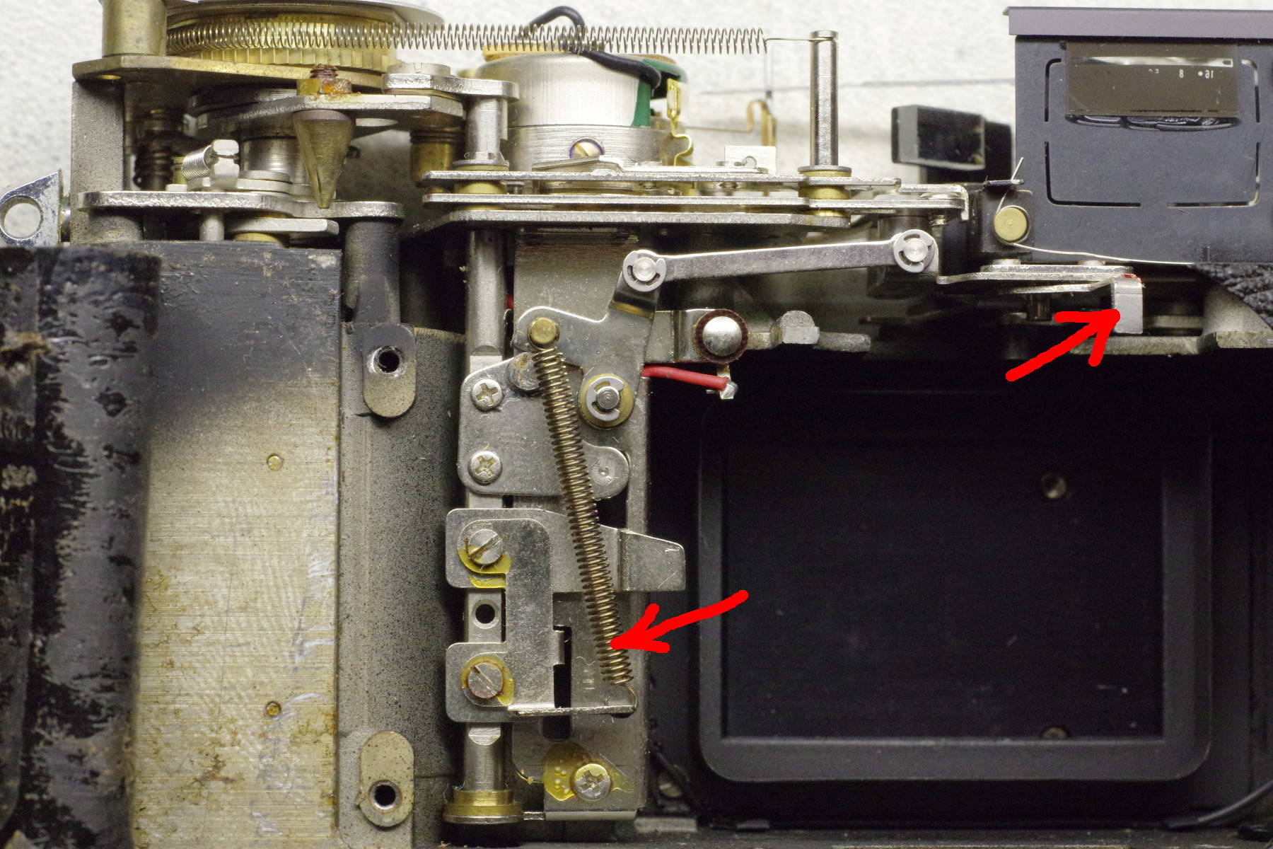 |
Remove the top and bottom covers, peel back the front leatherettes, unscrew the four screws securing
the shutter plate to the body, and pull off the shutter assembly. After removal, this is what you’ll see.
Remove the long spring identified by the left red arrow.
Note the lever identified by the right red arrow. It is difficult to align correctly
when reinstalling the shutter assembly, so it’s best to remove it.
|
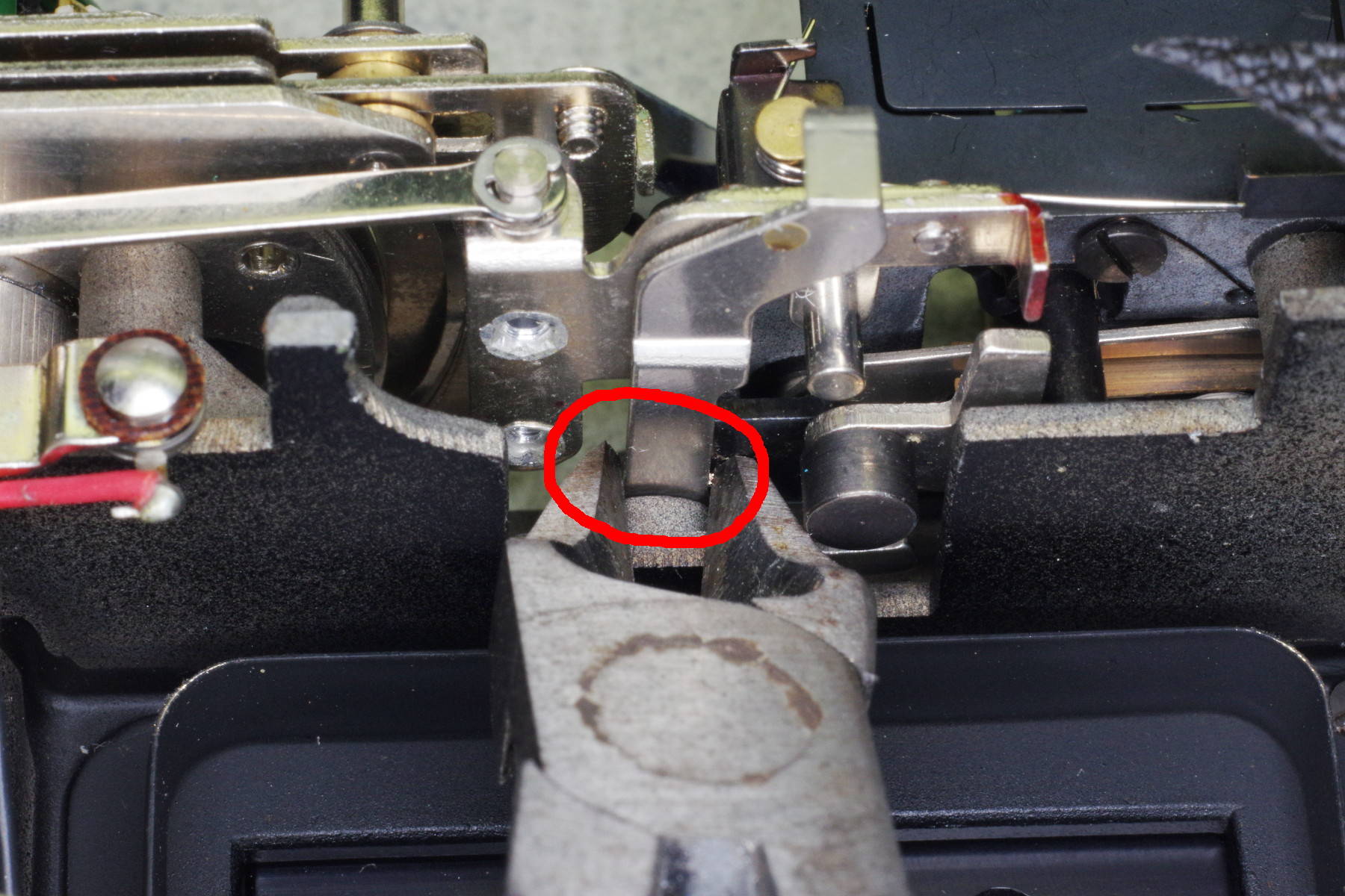 |
It’s made out of soft steel, so you can cut it by its pivot using a small wire cutter as shown.
|
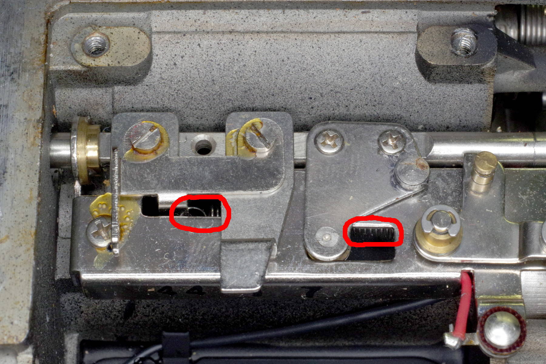 |
Here is a second spring contributing to excessive button force.
It is almost completely hidden under a long metal plate, but you can remove it
by first removing the shutter-release plate located above the left red circle.
As you can see in this photo, this is actually a sandwich two plates: The upper plate
holds the spring you wish to remove, and the lower plate is the shutter release.
Mark the position of the lower plate (it’s adjustable), and remove both plates,
taking care to not let the spring retract under the long plate.
|
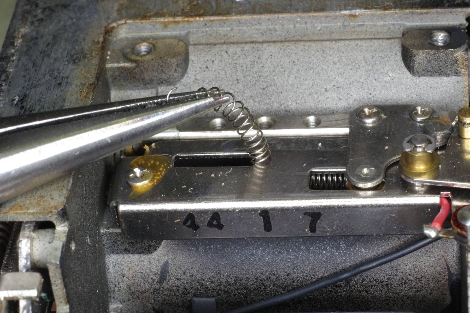 |
The sandwich of plates is gone, giving you space to
hold the spring with a needle-nose pliars having a serrated tip, and to pull out the spring.
This method of removal is crude, but it eliminates some disassembly.
|
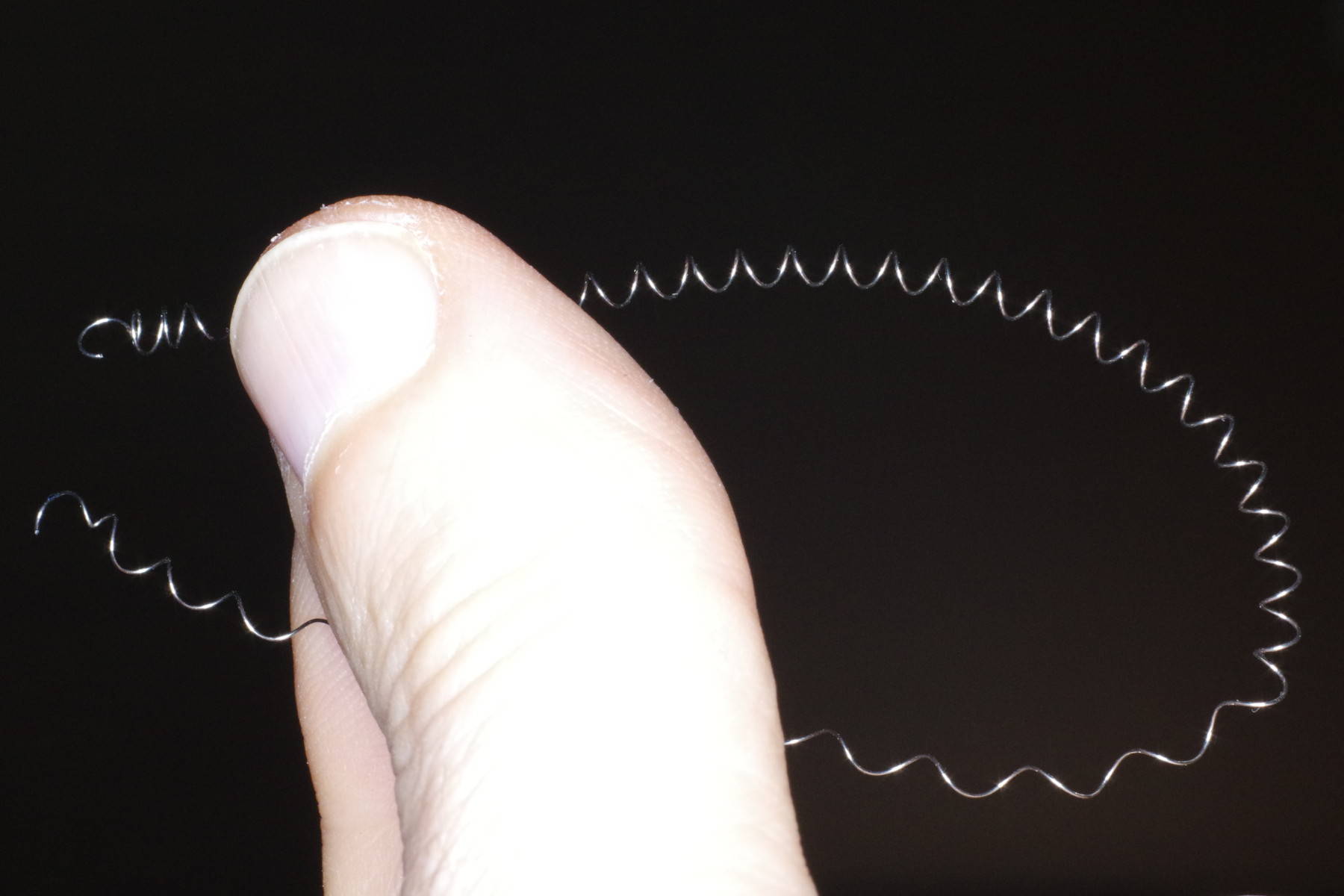 |
The spring is out.
|
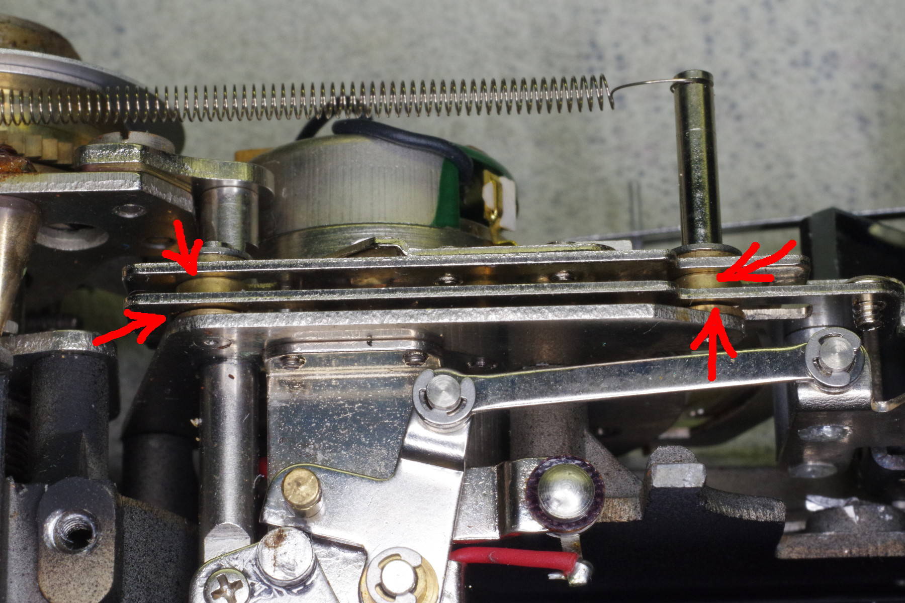 |
The heart of the automatic exposure mechanism is two sliders made out of stamped sheet metal,
separated by brass spacers marked by red arrows in this photo. The sliders move leftward, and you want
them to stay in their position at the right end of their travel. Apply a drop of Superglue (or equivalent)
to the brass spacers at the four spots indicated.
You probably only need to glue one or two spots, so the extra spots provide sureness.
|
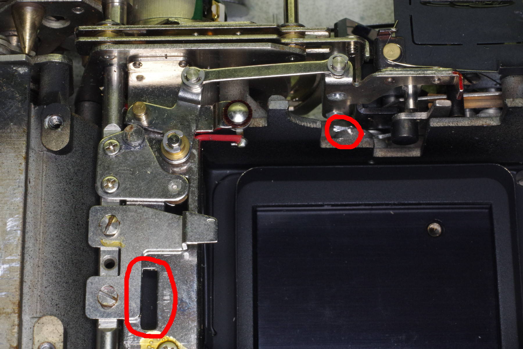 |
Here is the body after making these modifications.
By the left red circle, you will note that I reinstalled the release plate but not the
spring-holding plate that sat over it, as it’s no longer needed.
Note that the release plate is adjustable by virtue of its elongated screw-slots.
If you did not mark the position of this plate, fasten it in the center of
the slots as shown.
The right red circle shows the remnant of the lever that was cut off.
|
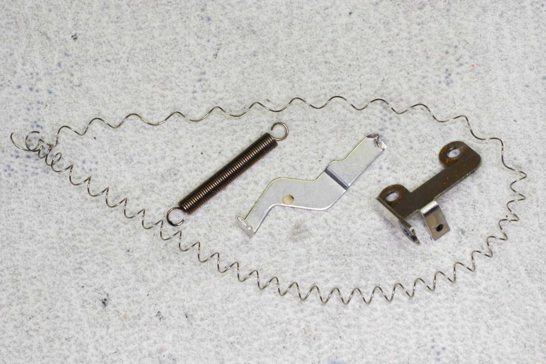 |
Here are the parts that will be left over. We are done with this modification.
|
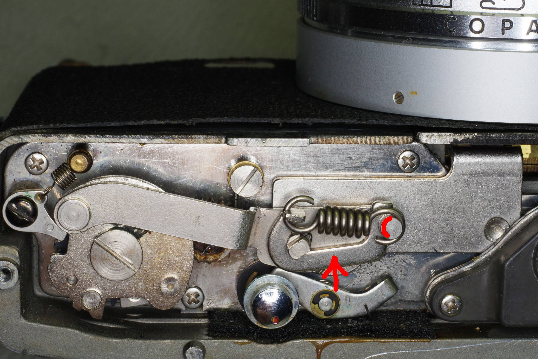 |
On a different subject,
my camera would not reliably cock its shutter, especially when focused closely.
After verifying that the cocking ring on the shutter was not bent,
I modified the link identified by the red arrow.
This link has a semicircle cut into its right end (not pictured), which mates with the
stud marked by the red arc. This red arc shows the position of the semicircle in the link.
Using a Dremel, I made the semicircle a little deeper, allowing the cocking mechanism
to move slightly farther.
|
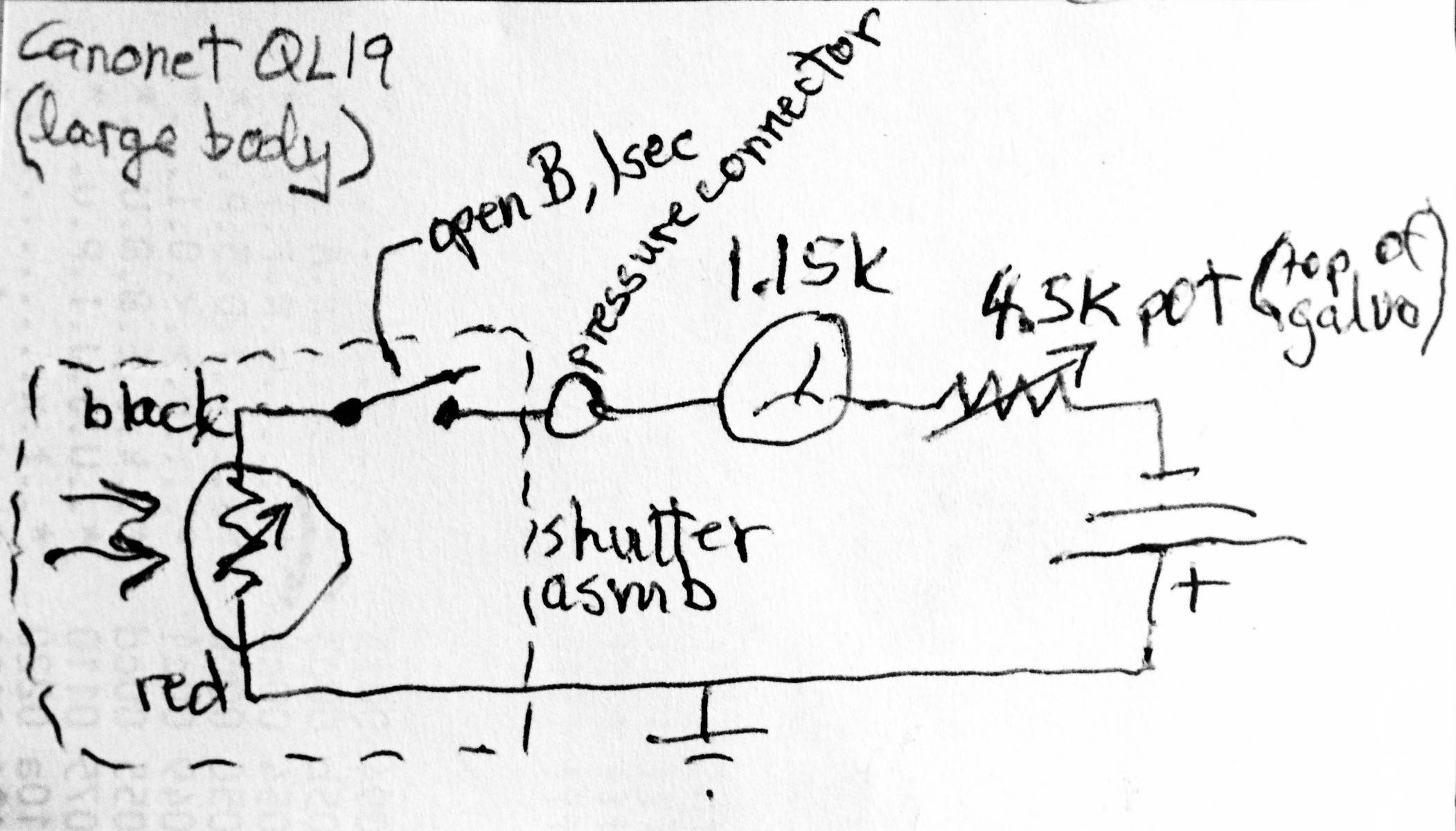 |
I also had trouble with the meter, and scribbled a schematic for it.
Here it is for your benefit in case you need to repair the meter circuit.
There is a switch on top of the shutter that opens when speeds of B or 1 are selected.
I discovered that the contacts in this switch were not closing, even when they were touching.
I cleaned those dirty contacts with a bit of emery paper.
I also bent a brass contact-arm in the switch slightly so they would touch slightly sooner.
Also, the red wire to the CdS cell (left end of schematic) was not grounded,
so I ground that end of the cell directly by removing its insulator, bypassing the wire.
Two final notes: You can extend the life of the battery by setting the shutter
to B or 1 speeds, disconnecting the meter. To do so, you’ll need to
depress an interlock-tab located above the self-timer lever.
Also, the CdS cell is likely to last longer if it’s not exposed to light
in storage. If you don’t have a lens cap, set the ASA to 25 and the shutter speed to 500.
These settings cause the mask over the cell to allow minimal light to strike the cell.
|