The auto-collimator works by projecting an image at apparent-infinity into the camera's lens. The image forms on the film, and reflects off the film and back out the camera's lens. A half-silvered mirror in the auto-collimator transfers this film-image into an eyepiece which you can view. This feature of seeing the reflected image is the auto part of an auto-collimator. The auto-collimator consists of a back-lit target image and a lens in front of it at its focal length. The lit image goes out the lens at apparent- infinity. If you look into the lens, you can see the image. It enters the camera under test, and forms an image on the film. This image reflects off the film, and some of this reflection makes it back out the camera's lens. It then enters the auto-collimator's lens. The auto-collimator has a half-silvered mirror between its lens and the target at 45 degrees. The returning reflection bounces off this mirror, and can be viewed using an eyepiece for a binoculars or telescope. Thus, you can see the actual image on the film, enabling you to calibrate the focus of the camera and to gauge the quality of its lens.
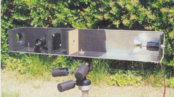
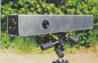
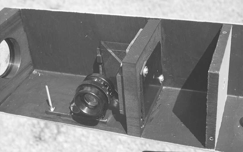
Click here for a larger picture of the parts. This picture says it all.
Enclosure: The whole enclosure is about 2.5 feet long, and about 4 inches on each side (inside dimension). Wood is probably fine, but expands and contracts with changes in humidity, which might (but probably won't) affect accuracy significantly. I used two pieces of 1.5mm-thick sheet aluminum. Each piece was bent 90 degrees the long way, so that when put together they formed a 2.5 foot-long box. The box contained the following.
I painted all surfaces black except the area near the light. Using flat black paint minimizes internal reflections, yielding best contrast.
Light: Start with a light at one end of the enclosure. I mounted it on a 4-inch square block of plastic (wood would be fine). A 50-watt miniature spotlight (with reflector) worked well for me. It cost $12 at the grocery store, and is worth it for this application.
First light baffle: About 9-12 inches away from the light is the first light baffle, which is simply a 4-inch block of wood or plastic with a 1/2 inch hole drilled in the middle.
Second light baffle: About 2 inches away from the first light baffle is the second light baffle, which is identical to the first light baffle.
I found that it requires two light baffles to suppress all extraneous light. In his camera repair book, Tomosy describes how to make a auto-collimator. But his design includes no light baffles, so contrast was low due to all the extra light blasting into the optics. I initially followed Tomosy's design, but quickly discovered that one light baffle greatly improved contrast, and that two baffles improved it even more because some light sneaks around the four sides of the first baffle, and because two baffles creates a less dispersive light beam.
Mask: Install a mask with a 3-4mm hole onto the light side of the second light baffle. The mask faces the first baffle, and is mounted on the second. I used thin black plastic for the mask. You'll want the mask to be adjustable over a few mm. Through its hole will pass a thin beam of light into the optical components. The diameter of the mask is a compromise: A larger diameter lets you see more of the target, but the additional light reflecting off the lens reduces contrast. Use the smallest diameter you can.
Click here for a picture of the baffles and mask.
Target Assembly: As described below, the target and the mirror are both mounted on the dark side of the second baffle (the mask is mounted on the other side). What I call the "target assembly" consists of the mask, baffle, target and mirror.
Calibration will be necessary, so the target assembly can be made to be adjusted back and forth a little. I cut slots in the sheet aluminum enclosure with a Dremel to provide for the adjustment. An alternative is to make the target assembly notadjustable, and make the lens adjustable instead, which might be easier to construct.
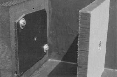
Target: A clear piece of plastic, such as a piece cut from a CD jewel case. Rub a piece of coarse sandpaper across the middle twice, at right angles, providing a hatch-pattern of lines. Mount the target with the scratches onto the baffle with the scratches facing away from the baffle. Be careful not to get any scratches on the back of the target (to avoid accidentally focussing on them). The scratches will appear as black lines in the eyepiece, and you will calibrate the camera's focus to make them as sharp as possible. I supported the target by three screws with springs underneath, allowing the target to be adjusted by turning those mounting screws, permitting fine calibration of the auto-collimator (moving the whole target assembly is the coarse calibration).
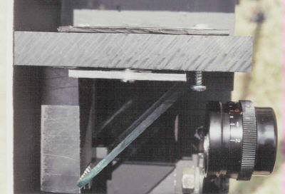
Click here for a top view of the target assembly and eyepiece. You can see a gap between the target and baffle, and can barely see the spring-washer pushing the target against the screwhead in the center of the photo. Fine adjustment is done by turning that screw. (The screw on the right is merely to keep the mirror from falling out in case the auto-collimator were turned upside-down).
The target must be positioned at the focal length of the lens. So you should install the lens first, and then decide where the target assembly is to be positioned. If you're measuring distances, keep in mind that the mirror increases the focal length by 1-2 mm.
It would be nice to use a test-pattern as a target, instead of scratches. But it needs to be about 3mm diameter (same as the mask). You could take a picture of a standard lens-test pattern onto slide film from an appropriate distance, and use the mounted slide as the target. Take the picture with a very sharp lens and a tripod; you don't want a fuzzy target.
Half-silvered mirror: At least 1.5 inches square, so that the reflected light will cover the entire rear optic of the eyepiece, with a little room to spare for mounting. Edmund Scientific carries them, and American Science and Surplus also has them on occasion. I used the 50% reflectance kind. Make sure the reflective surface is facing away from the target (i.e., toward the eyepiece).
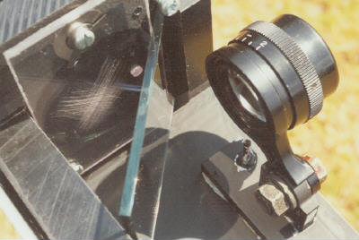
Click here for a photo of the mirror, target and eyepiece. The scratches on the target are plainly visible.
I mounted the mirror to the second baffle at 45 degrees by carefully cutting and gluing scrap blocks of plastic with Super Glue. Avoid vinyl; Super Glue adheres poorly to it. Try to position the mirror as accurately as possible both horizontally and vertically, by measuring angles carefully. Any inaccuracies must be compensated by adjusting the postion of the eyepiece. If you opt for an adjustable lens (instead of an adjustable target assembly), then the mirror need not be mounted to the baffle; it can be mounted to the enclosure instead.
Eyepiece: This faces the mirror, at 45 degrees to it. So the eyepiece is at 90 degrees from the baffle. Use an eyepiece from a binoculars that has diopter correction. I suppose a focusable eyepiece assembly from a telescope would work. Mount so that some horizontal and vertical adjustment is possible for accurate centering. The position closer/farther from the mirror must be selected for sharp focus, so don't commit to a position until you've done a rough calibration.
Lens: This is installed at the other end of the enclosure. I suggest that it be at least 150mm focal length and 20mm diameter, and preferably 200mm or longer. It must be a color-corrected achromat (two elements glued together). And it must be coated to maximize contrast by reducing reflections. The front element of a high-power binoculars or low-power telescope should work. I bought a 185mm-by-54mm achromat from American Science and Surplus (that 54mm is about twice the diameter that's really needed). Edmund Scientific carries suitable lenses. I mounted mine by milling a 55mm hole in a block of plastic, gluing the ring from a 55mm filter in the front, and gluing the lens in behind it.
If you can mount the lens somehow to be adjustable, then you will not need to make the target assembly adjustable. A helical-mounted lens will make the auto-collimator easier to calibrate than by moving the target assembly. Consider adapting the helical from a parts-camera for this purpose.
Some of the contrast-reducing flare in the auto-collimator comes from the main light bouncing off the inside surface of the lens, off the mirror and into the eyepiece. I thought that if the lens is rotated sideways a few degrees, this reflection will not enter the eyepiece, yielding higher contrast. I tried this, and contrast improved some. But since the lens is not corrected for aberrations (except chromatic), using the lens a little off-axis might reduced sharpness enough that I do not suggest rotating it.
I installed a tripod-mount. I used two tripod nuts from the bottoms of old camera cases, screwed into each other, locking onto the sheet metal, and glued with Super Glue for good measure. I use the auto-collimator on a sturdy tripod, with the test camera on a second tripod.
The mirror chamber must be as dark as possible for best contrast, so after calibration and adjustments are done, this area at least should be enclosed. To prevent light from the spotlight from shining on your face, I suggest that the entire auto-collimator be enclosed. Doing so will also keep dust off the optics.
At this time, you should also adjust the mask so the image is centered in the camera's groundglass. For this step, it's crucial that the camera be perfectly straight and centered with respect to the auto-collimator's lens.
Now the eyepiece must be adjusted for centering and focus. Set-up a camera for calibration (with film in it, shutter open, and focussed at infinity), turn on the light, and make sure the camera is straight and centered as above. Move the eyepiece until the image is centered and brightest in the eyepiece. Then adjust its knob sharpest focus.
For calibrating focus, I've found that setting the f-stop halfway between f/4 and f/5.6 is best. This provides the best compromise among brightness, contrast, freedom from aberrations in the lens, and depth of field.
You can easily adjust the camera for best sharpness in the center of the negative. But for rangefinder cameras, you can turn the camera some so that you're seeing a spot about a third or halfway between the center and corner of the negative, and calibrate there. This can be more accurate because many lenses have a curving field of focus, so calibrating off-center produces sharper average focus over the entire negative. If you examine the factory's focus-settings of a few rangefinder cameras, you'll notice that at infinity, the center of the negative is typically focussed slightly past infinity. The desire for best overall focus is the reason why.
By looking at the image from center to corner of the negative at various f-stops, you can gauge the sharpness of the lens and its flatness of field. Most lenses are sharp in the middle, although many lose contrast wide open. And you would expect a lens to get uniformly worse as you move away from the center and reach the corner. But that's not exactly what happens.
Yes, most lenses get uniformly worse as you move away from the center. But approaching the corner, a surprising thing happens: Sharpness suddenly improves, and then rapidly gets worse as you reach the corner. What's happening is that the field of sharp focus has curved back to the point at which you're focussed (infinity), so you see a point at perfect focus again near the corner. But the field is sloped steeply here, so it rapidly moves away, causing sharpness to degrade rapidly very near and at the corner.
If you adjust the camera's focus for best sharpenss in the center, then there will be a point of worst sharpness somewhere between the center and that second point of good sharpness near the corner. You can calibrate the lens so that this worst point gets better, and the center gets worse. In fact, you can make the center and worst point equally unsharp. This means you have split the difference between the best and worst focus points, which gives you the best average focus over the negative. From what I've seen, this is what most manufacturers of rangefinder-cameras have done.
An easier way to do this is to note the position of worst focus, and rotate the camera to be halfway between center and that position of worst focus. Then calibrate the focus there.
Tomosy recommends putting a mirror in the back of the camera being calibrated (presumably to yield a bright return-image). I recommend against this because the actual position of the film is generally a few mils farther back from the camera's film-rails, because most cameras have a gap between the pressure plate and the rails (believe it or not, the pressure plate does not apply pressure in modern cameras). This difference of a few mils makes a significant difference in accuracy. Also, you'll lose the ability calibrate off-center and to gauge the quality of the lens.
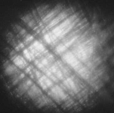
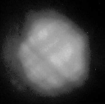
Notice the grain in the bright areas of the right half of the second photo above. This is the texture of the emulsion of the film in the test-camera! Most decent lenses show this grain clearly in the center. (The grain in the next two shots were due to my poor exposure).
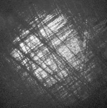
Now I rotated the camera sideways so the auto-collimator's image was at the edge of the negative. The first photo is wide open, the second stopped down to f/5.6.
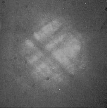
These photos have poor contrast because little light bouncing off the negative makes it back into the camera's lens (on the edge, the light tends to bounce away from the lens). Because the image returning into the auto-collimator is so dim, any stray light in the auto-collimator reduces contrast. Without the light baffles, these images would not be visible. When building your auto-collimator, do all you can to eliminate stray light. Also, these photos were taken in a dark room to eliminate ambient light.
As you might have guessed, performance at the edge is what separates good lenses from the others. Most lenses are sharp in the middle when stopped down. Many do reasonably well in the center wide open. But the edge is tough. As mentioned above, some lenses soften as you pan the camera from center to edge, and then get sharper at the edge, due to curvature of field. So look all across the negative, not just at the center and edge.
All the photos on this Web page were taken with a Zuiko 50/1.8 on my OM-1. For the above auto-collimator images, I simply focussed the Zuiko at infinity, pointed it into the eyepiece, guessed the exposure, and hoped for the best.
Use a better test pattern. A lens-cleaning cloth sandwitched between two pieces of clear plastic might be a good pattern. Or maybe a piece of microfiche. Or a slide with a test-pattern on it.
Put a fan in the light chamber because it gets too hot if left on for more than 15 or 20 minutes. The two light baffles shield the target from much of this heat, so it actually shouldn't be harmful. But when the aluminum case gets too hot to touch, I get nervous.
Use a 20mm diameter lens instead of 54mm. The lens only needs to be large enough to cover a 50mm f/2 camera-lens, so the extra diameter merely lets in more ambient light, reducing contrast. Note: If you calibrate lenses with large front diameters, then a large diameter lens on the auto-collimator might be appropriate.
Use a better lens. The front coating on my surplus lens came off when I cleaned it with lens cleaner, increasing reflections and decreasing contrast. Buy a good coated (preferably multi-coated) achromat from Edmund Scientific.
Use a lens with a longer focal length of perhaps 300mm. This would allow calibrating a 100mm lens on the camera since the 3X difference in focal lengths would allow sufficient accuracy. Yes, this means using a 900mm lens to calibrate the auto-collimator, but that's what teleconverters are for.
He also sells an accurate yet inexpensive shutter-speed tester. I purchased one and strongly recommend it. Click here for more information about it. This link takes you to Camlogix.com.