Sadly, the cocking racks are weak in folding Retina cameras, and these shutters
require high cocking-force. The M-sync mechanism is a significant contributer to that high force
because it contains a strong spring that is extended at the worst possible place in the cocking
cycle. At end of the cocking stroke, when the mainspring is putting maximum force on the rack,
the strong M-sync spring is stretched, adding significantly more force, helping racks to fail.
You can verify this claim of increased force by manually cocking the shutter using the
cocking tab on its perimeter, and feeling the increase in force near the end of the stroke
as the M-spring is being stretched.
The shutter itself is quiet, free of vibration, and reliable. Well, it used to be reliable,
but after all these decades, a couple of important springs have weakened,
often causing these shutters to fail in several ways:
This article describes a modification which solves all of these problems.
The only disadvantage of this modification is that your shutter will no longer
have M-sync; it will be synchronised for X only. So if you want to pop flash-bulbs,
you must shoot at 1/30th or slower. This is a minor disadvantage because it only
prevents the use of bulbs at 1/60th or faster, which you will probably never
do because when shooting indoors, it’s wise to use a slow speed to admit
more ambient light to fill in shadows from flash. All other features of the shutter,
including the self-timer, will still operate as designed.
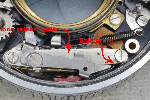 |
Remove the plates and rings from the front of the shutter until you are seeing this.
Note that I also removed the release-lever on the right side.
Disconnect the left end of the hairspring (labeled in red), so that it won’t fly away
when you remove the right screw securing the long release-plate. Now remove the long release-plate.
|
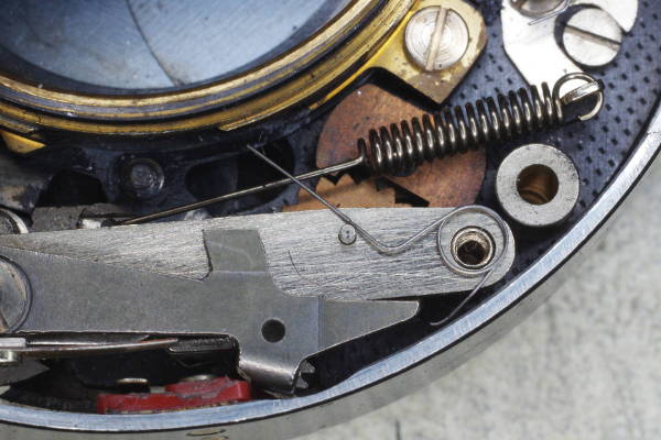 |
It is easier to remove and reinstall the hairspring by first not only disconnecting it,
but also positioning it as shown. The screw may then be removed or installed without
the hairspring shooting away like a squirted watermelon seed.
|
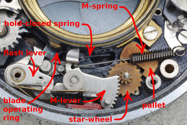 |
Here’s what you’ll see after removing the long release-plate.
The arrow marked “blade operating ring” points to a tab on that ring;
the ring itself encircles the entire brass throat, and as its name suggests,
it operates the blades.
The hold-closed spring is mostly a straight wire with a jog in the middle.
The angle holds the blade operating ring closed, as you can see in this photo.
The hold-closed spring presses hard against the blade operating ring,
thus adding considerable friction to the ring,
often causing it to be sluggish or to stick. You will remove this hold-closed
spring because another spring accomplishes the same purpose of holding the
blades closed during and after cocking the shutter.
|
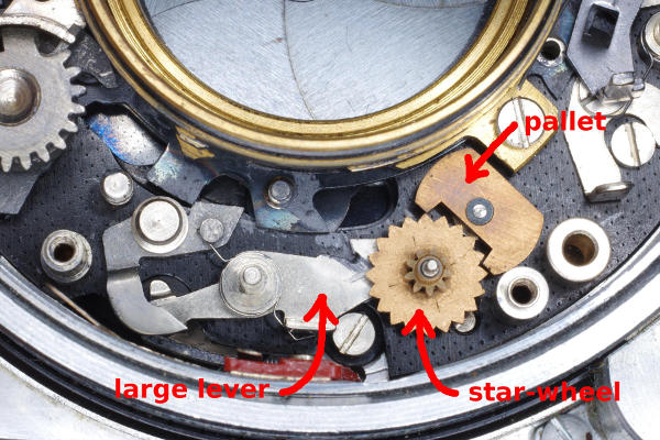 |
Remove parts from the flash-sync section until you are down to this.
To remove the hold-closed spring, first lift its short end off of its
supporting post. Then it can be lifted out.
Note that the star-wheel remains in the shutter, even though it can easily be removed.
It must be present in order to prevent the pallet from rotating
too much and obstructing the blade operating ring.
|
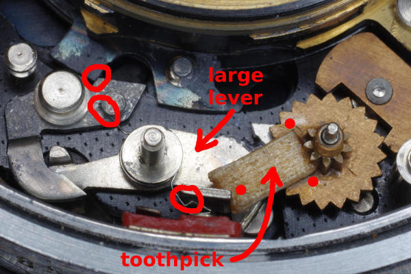 |
The large lever (labeled in this photo) needs to be locked into its fully clockwise position because
when it’s in its anticlockwise position, it prevents the shutter from firing.
A good way to lock it fully clockwise is to place a piece of toothpick into the pictured position.
The piece should be 4.5 mm long, and no more than 1.1 mm thick. If it’s any thicker,
it will interfere with the tab on the long release-lever. If yours is too thick,
you can make it thinner by squeezing it between the jaws of a smooth-jawed
needle-nose pliars. A hint: First place the left end of the toothpick into the correct position,
and then press down on the right side until the toothpick sits flat on the
star-wheel. That will cause the left end to rise a little because there is extra space under it
on the left side. The toothpick’s fit should be snug.
Apply drops of Superglue at the three red dots to ensure the toothpick will not slip off.
I also covered the top of the toothpick with Superglue so the glue would soak into the wood,
turning the toothpick into a solid chunk of plastic.
An alternative method I’ve not tried is to solder a piece of thick wire to the
star-wheel and file a “V” into its left end so it will lock itself in place while holding the
large lever fully clockwise. Unlike soldering, an advantage of using the toothpick is that this modification
is easily reversible: One would simply soak the star-wheel in acetone to remove the glue,
and then reinstall the parts that were left out.
The two lower red circles identify the ends of a tiny spring.
Make sure they stay in these positions, because this spring will be your new hold-closed spring.
The left end of the spring presses against a lever at the left, rotating it anticlockwise,
causing it to push against the blade operating ring (top red circle).
This modification causes this lever to always press against the blade operating ring.
Consequently, this lever and the spring together always hold the blades shut,
even when the camera is jarred with a knock (which I tried on two cameras).
Thus, you no longer need the hold-closed spring,
eliminating troubles due to its added friction on the blade operating ring.
|
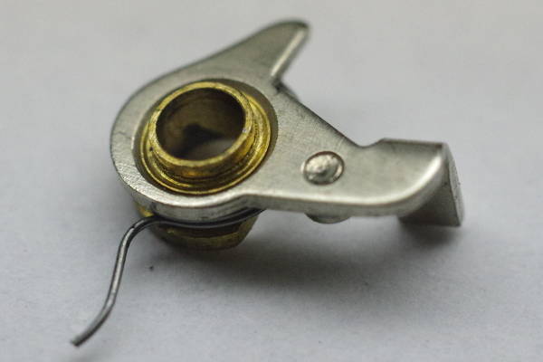 |
Here is a close-up of one of the levers you removed earlier.
Remove the spring that is attached to this lever.
|
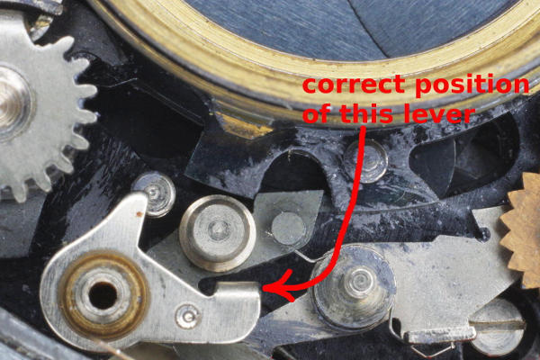 |
Here is the correct position of the lever on the left (that was mentioned in the prior step) which must be put back.
Note the position of its tail-tab on its right side.
Now you must put back the flash lever and long release-plate, along with its
hairspring. Then reattach the cocking ring to the front of the shutter.
|
 |
When firing at the highest speeds, the cocking ring will not allow the mainspring to push the blades completely closed,
causing the blades to finish closing on their own momentum. I regard this as poor design. The hold-closed spring then
performs a second duty: It prevents the blades from bouncing back open a little. In fact, preventing bounce-open might
be the main reason the hold-closed spring is present, so perhaps it should be called the “anti-bounce spring”.
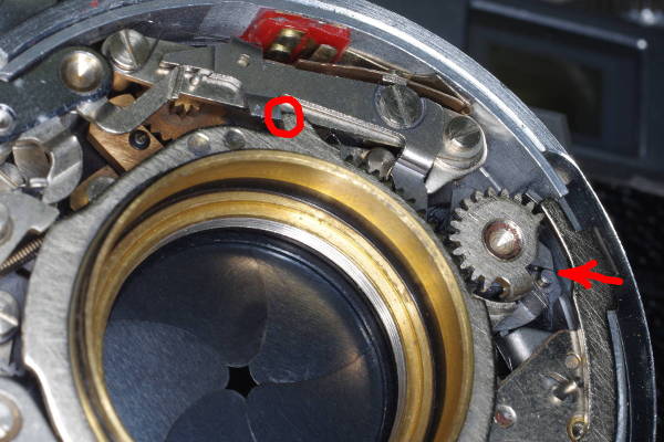
But because the hold-closed spring is gone, the blades can bounce back open until
their closing pin strikes the closing cam driven by the mainspring, shown at the right arrow.
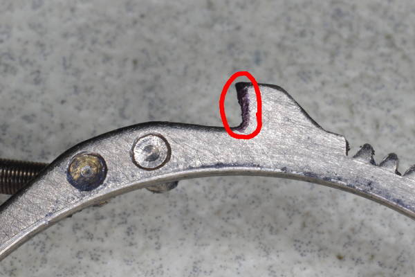
After removing M-sync, you can easily simulate bounce-open yourself by cocking the shutter enough
to latch the catch circled in red, and then pushing up on the round closing pin until it touches the closing cam.
The red arrow shows them touching. The shutter will probably be slightly open, as you see in this photo.
The solution is to remove 0.3 to 0.5 mm of metal off the edge of the tab on the cocking ring
shown in the red circle on top. Doing so will cause the cocking ring to place the closing cam
a little farther in its cycle, not allowing the blades to bounce open enough to allow any
light to pass through.
|
 |
To help me remove the correct amount of metal from the tab, I put 0.5 mm of ink on the edge to be shrunk
using a felt-tip pen (a Sharpie). Note that this edge is at an angle, so be careful to
maintain this angle when removing metal.
If you remove too much metal (around 0.8 mm or more), then one or both of the following features of
the shutter will change: (1) The firing lever will not depress, even though the shutter
is cocked; and (2) the self-timer will start running immediately after being armed,
instead of waiting for the shutter-button to be pressed. Both of these problems can be fixed easily
by filing or grinding the appropriate edges, but why make extra work for yourself?
After grinding the metal from the tab, check both conditions above (lever won’t depress or
self-timer runs upon arming). On one shutter I modified, removing 0.5 mm from the tab was enough to make
the self-timer run, forcing me to grind a bit of metal off its tab on the cocking ring.
|
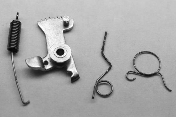 |
Here are the parts that you will not put back.
These are (from left to right) the (1) M-sync spring, (2) M-sync lever, (3) hold-closed spring, and
(4) a small M-sync spring.
|
You now have a shutter that exerts significantly less force on the cocking rack of a folding Retina,
making the camera more reliable. And the shutter itself is more reliable because:
With a reliable rack and shutter, you can shoot with confidence.