 |
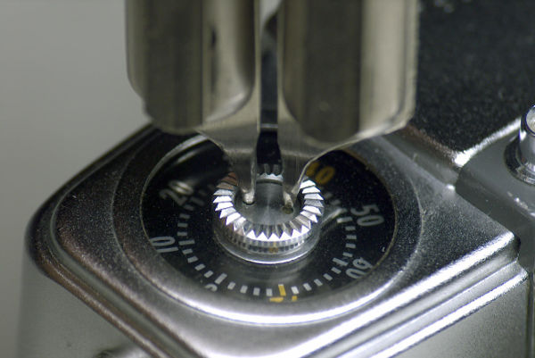
If you're going to disassemble one of the older Pens having this pin-face screw in the frame-counter,
then whatever you do, use a proper spanner wrench for it with round tips as shown.
Also, before turning the spanner,
ensure that it is fully seated in both holes by gently rocking it back and forth. Doing this
will prevent ugly tool-slip marks on the screw that tell folks "an idiot has tampered with me."
|
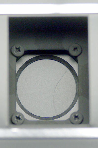 |
On the Trip, in order to remove the front assembly, you removed four screws on the large shutter-plate.
But on the Pen, with the back off or open, you'll see four screws as shown around the shutter-blades.
Unscrew them, and the front assembly comes off.
|
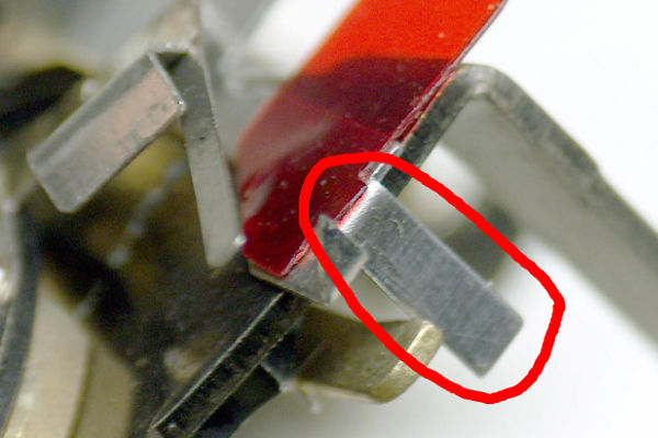 |
To defeat the auto-mechanism on the Pen, you only need to remove the silver-colored tab
that is circled in red. I suggest using a wire-cutter.
|
 |
After it's been cut off, it won't interfere with the movement of the speed-lever.
You don't need to break off half of a lever as we do with the Trip 35.
|
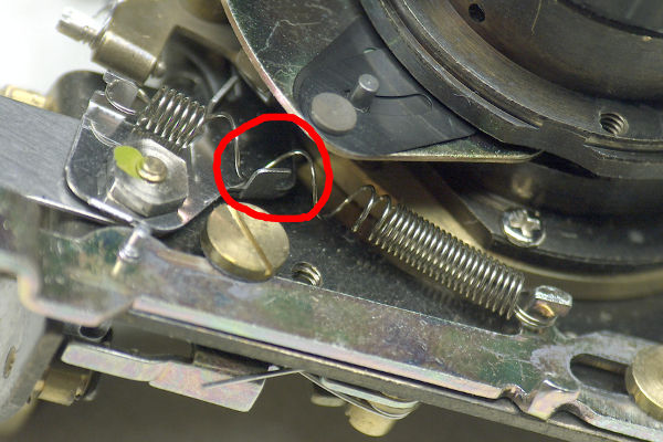 |
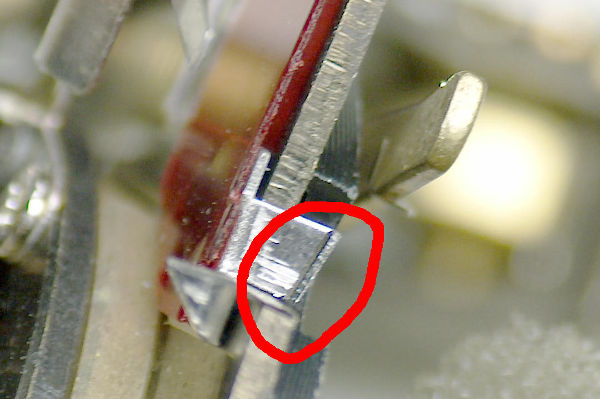
Remember the three springs on the front of the Trip's shutter-plate?
You have the same springs in the Pen. Remove them.
And attach the longest spring as shown.
Note that I stretched this spring so as to avoid a tab (circled in red) that was
interfering with the spring.
If you don't want to stretch the spring for some reason,
you can bend the tab over or cut it off.
|
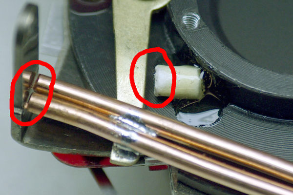 |
My notes say to make the copper weight-wire 33mm long for Pen models having removable backs,
and 43mm long for models having hinged backs (such as the EES-2).
The problem we face is how to limit the travel of the speed-lever in both directions.
In this photo, I solved these two problems as follows:
(1) I positioned the wire so it will hit the viewfinder support tab on the left (left red circle).
This is partly why the wire is longer than the Trip's 24mm wire.
(2) I glued a small bit of material (right red circle) onto the plate to limit downward motion.
|
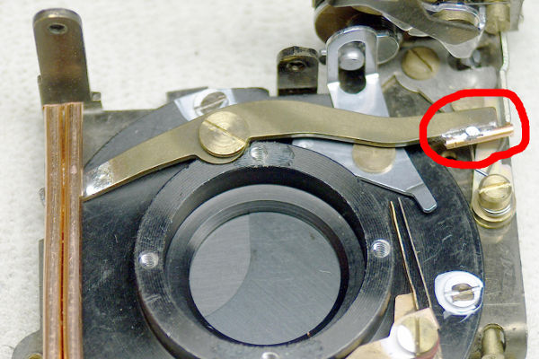 |
Another solution I tried was to solder a bit of wire on the right side as shown.
The problem is that the body-casting is close to the right, so you must position
this piece of wire accurately.
|
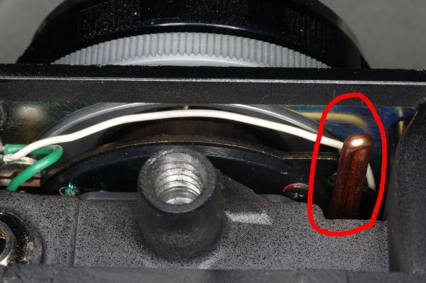 |
I suspect that you need not bother with the downward stop at all, because as the wire
moves down, it will be stopped by the bottom-plate of the camera. As you can see, the 43mm
wire protrudes into the bottom-portion. Likewise, for models with removable backs, the 33mm
length will hopefully be stopped by the floor of the body-casting. But double-check these
numbers (33mm and 43mm), as I measured them a decade ago and I don't recall clearly
whether they correctly accommodate stopping on the floor.
|
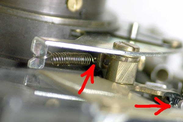 |
Here's some good news: The spring to hold the aperture open is easier to move than with the Trip.
There's already a coil spring holding the aperture closed. You will grab the right end of it
(left red arrow) with a needle nose pliars and hook it to the aperture-calibration screw
(right red arrow).
|
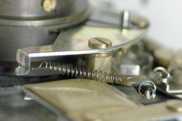 |
Here's the spring after its right end was moved.
|