Preventing Rack-Damage in Retina IIIc/IIc/Ib Cameras
Mark A. Overton, Aug 1, 2020 Return to main page
Most of us know that the Retina IIIc/IIc/Ib cameras commonly suffer from stripped cocking racks.
This article describes how you can prevent a rack from stripping.
Before proceeding, I must mention that this page is intended for experienced camera repairmen,
so it does not describe the tools you will need
nor does it provide step-by-step instructions for common operations such as removing the camera’s top-cover or meter.
Chris Sherlock has kindly created some videos on Youtube showing how he disassembles
and repairs cameras. I recommend them! To help you gauge his competence, you could
pour a bunch of Retina screws and springs onto his workbench, and he could tell you
where every one of them should go.
Here is a video on disassembling a Retina IIIc.
Here is a video on assembling a Retina IIIc.
Now, let’s look at what happens to that rack when you operate the advance lever.
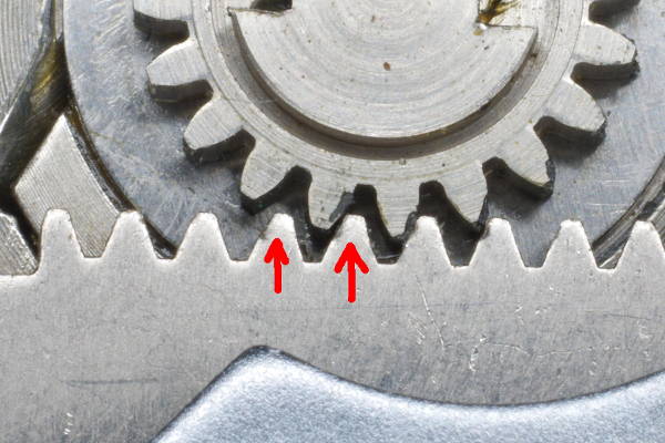 |
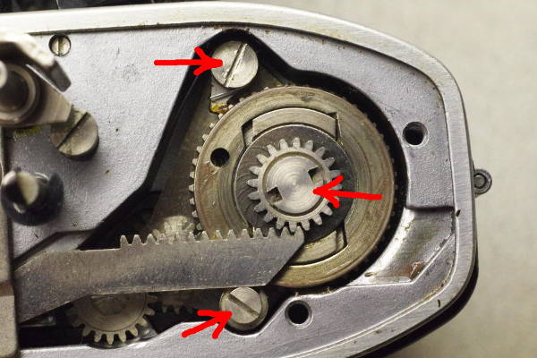
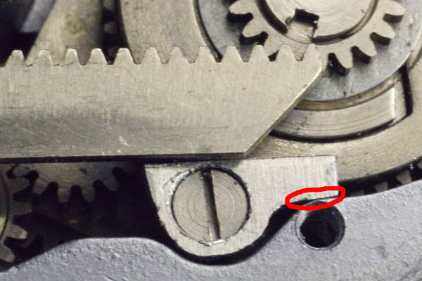
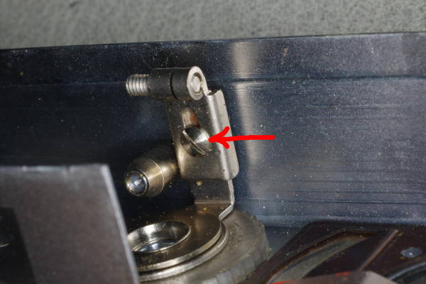
This is a Retina after removing the top-cover, meter, and rack cover-plate, revealing the vulnerable
cocking rack at a mid-advance position.
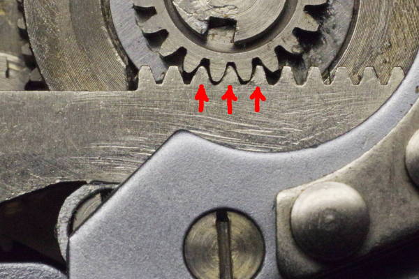
As you can see, the pinion gear is riding on the tips of the rack’s teeth.
Because (1) that gear is steel, (2) the rack is brass, (3) the cocking force is high, and (4) the back of the
rack is poorly supported, the tips of the rack’s teeth
deform slightly each time you advance the film. This deformation occurs in the teeth
on the left side of the rack because that’s where cocking force for the shutter is highest.
You can see that the two teeth marked with red arrows
are bent slightly rightward due to high force on teeth-tips. Each roll of film will deform these teeth slightly more.
After a while, one or two tips will round off or break off, and you will have a stripped rack.
It gets worse. The rack has teeth at both ends, and the concealed lower teeth are also deform
and eventually strip for some of the same reasons: too much force too little support. In addition,
due to mechanical tolerances, the lower rack and pinion in many cameras only partially mesh, causing
the tips of the rack’s teeth to deform and strip.
|
Kodak’s engineers failed in four ways: (1) The tolerance-stack is too large because the
supports for both ends of the rack leaves the rack only partially meshing with the pinion,
(2) the rack flexes away because it’s not supported directly behind the driving pinion,
(3) the supporting post/plate itself flexes away because it’s flimsy, and (4) the small brass
teeth can only barely endure the high cocking force of the shutter.
These failures cause the rack to ride on the tips of its teeth,
deforming them and eventually breaking them.
The modifications described in this article fix these problems for both ends of the rack
by causing the rack to mesh fully, instead of riding on the tips.
The repairs described below not only prevent racks from stripping,
but they also make stripped racks usable again!
Only the tips of teeth are broken; the remainder of each tooth is fine.
These modifications cause pinion and rack teeth to mesh (engage) fully,
so the rack will function correctly even if a small amount of metal is missing from the tips.
Someone might argue that if the linkages for cocking the shutter are in-spec and properly
lubricated, the rack would not flex as much and thus would not fail.
Unfortunately, that’s only true in a perfect world. In our world, there are minor
manufacturing variations in parts that affect friction, and lubricants degrade over time,
both of which boost the force needed to cock the shutter. Therefore, the rack needs to
have margin, meaning it must be able to handle a higher load than one would encounter
in a perfect world. That’s why we need to strengthen the rack’s support.
Without the stronger support, the real world causes racks to strip.
SUGGESTION: High cocking-force causes racks to strip, and even after making the modifications
described in this article, I am not confident that the rack will endure the high cocking-force
for many rolls of film. Near the end of each cocking stroke, where cocking force is highest,
cocking force rises substantially in order to stretch the strong spring inside the
Synchro-Compur shutter for M-sync.
You can reduce cocking force by removing the M-sync mechanism from the shutter.
All other features of the shutter will still work, including the self-timer.
But the M-sync setting will behave like X-sync.
I strongly suggest that you remove M-sync.
Learn how here.
Your rack will thank you.
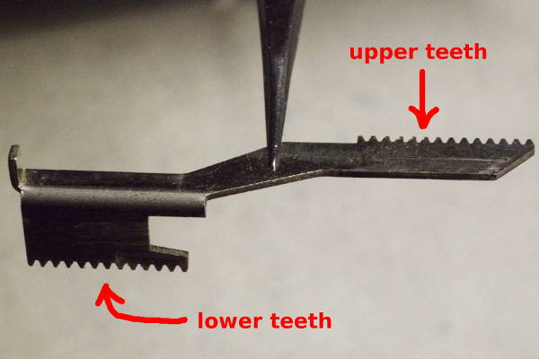 |
As mentioned above, the rack has teeth at both ends, and the support for both ends
needs to be strengthened. The ends are called the “lower teeth” and
“upper teeth”. When you remove the top-cover, you will see the upper teeth.
|
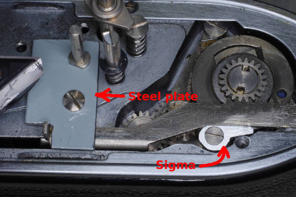 |
The remainder of this article tells you how to support the upper teeth with a “sigma”
and the lower teeth with a stronger plate, both of which are pictured in this photo.
It also explains how to expand the lower side of the rack to improve mesh.
|
Supporting the Upper Teeth with a Sigma
 |
First remove this plate that is held on by two screws.
This plate serves to hold down the rack, and also provides a strap-lug.
Throughout this article, I refer to this part as the “end-plate”.
|
 |
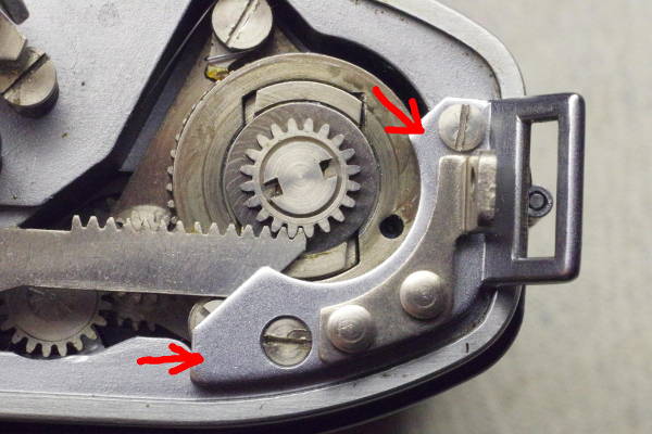
The end-plate has been removed.
IMPORTANT: Make sure that these three screws (red arrows) are tight!
If any of these screws is loose, the pinion gear (in the middle) can shift up and down
a little, creating more separation between rack and pinion despite the support
you will add below.
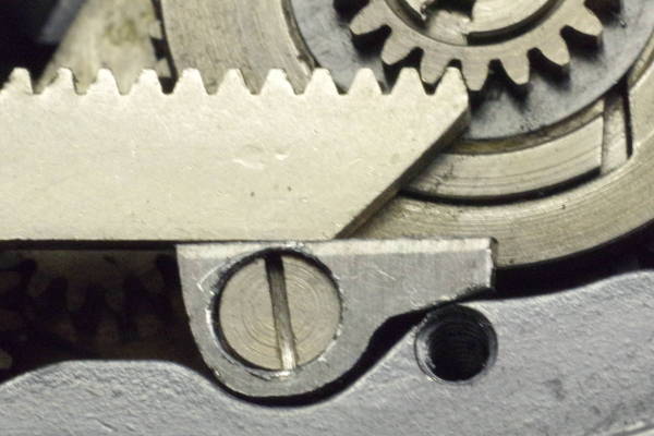
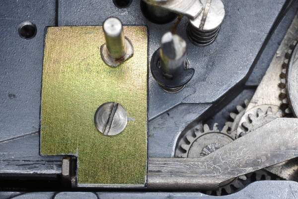
Take note of the post marked by the bottom arrow. This post holds down the advance
mechanism in the body. It also serves as the rear support for the rack, but its support
is poor because the post isn’t strong enough (so it bends away), and its support
is substantially off-center with respect to the center of the pinion, cause the rack
to bend away from the pinion. Both bendings reduce the mesh of teeth, damaging the
rack’s teeth.
|
 |
If your camera is a late production variant, it will have a thin plated brass pressing
over the body-casting. Notice that the pressing overlaps the sigma.
|
 |
To prevent the overlap from interfering with the sigma, you will need to remove
some material from the pressing as shown.
|
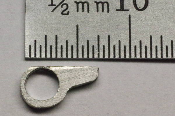
You will create a small part in the shape of a Greek sigma (σ) which will be
added to the camera, while not removing or modifying any other parts. Thus, this
modification is reversible.
You must drill a 3 mm hole. For a Retina IIIC (big-C), the hole will be about 3.1 mm.
If you don’t have a 3 mm drill bit,
drill a hole close to 3 mm, and enlarge it with a jeweller’s circular file until
the support post (which you must remove from the camera) fits in it. Try to not enlarge
the hole too much; the post should fit with minimal play.
You will create a sigma-shaped support out of 1mm-thick aluminum or brass sheet metal.
But if your camera has the thin plated brass pressing described above, the sheet metal should be 0.8 to 0.9 mm
thick.
If you have sheet aluminum that’s a little thicker than what you need, you will be able to
easily file the small part down to correct thickness. I would prefer brass because it’s
stronger, but aluminum is strong enough, and because that’s what I had on hand,
that’s what I used.
If you don’t have suitable sheet metal on hand, search the internet or amazon.com
for “aluminum sheet 1mm” or “aluminum sheet 0.040” (0.040 inch is 1mm).
As of 2020, you could buy a one-foot square sheet for about US$13.
Also, a search for “brass sheet 1mm” reveals multiple sellers of 100x100 mm brass
squares and larger starting at about US$7. One camera uses an 8x5 mm rectangle of sheet metal,
and assuming a cut is 1 mm wide, a camera would consume 9x6 mm of metal,
so a 100x100 mm square would repair 176 cameras. If you are willing to take the extra time
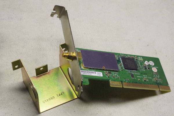
required to cut and file steel to shape, you can find 0.8 to 1.0 mm sheet steel in parts of an old computer.
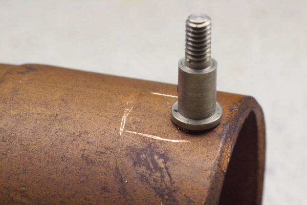 |
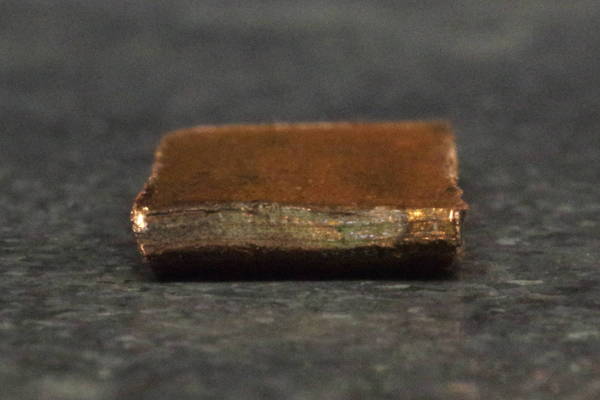
If you can’t find any suitable sheet metal and don’t wish to buy a piece,
you can probably cut a piece from copper pipe or a copper pipe-fitting as pictured.
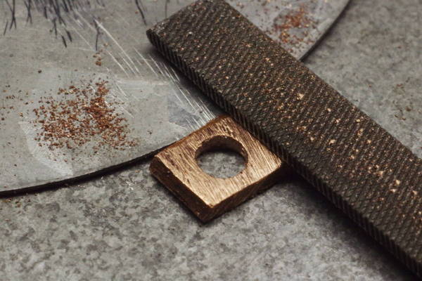
You must drill a hole in the sigma, and it’s easier to drill a hole in the pipe
instead of a tiny 8x5 mm piece, so drill a 3 mm hole first that’s at least 0.5 mm
away from the edge. Note that the edge on my piece was rounded, so that portion will be
filed off, so I drilled the hole 1 mm from the edge. The support post from the camera
is shown here in the hole.
Scratch (or mark) an 8x5 mm rectangle on the copper as shown in this photo.
Then cut out the rectangle.
|
 |
After cutting out the piece, it will be curved. You can remove this curvature by placing
two thin strips of pasteboard under it, securing them with tape, and
hammering on it a few times. (This is a different piece with no hole in it.)
The result of the hammering will be a flattened piece. The slight remaining curvature will be
removed when you file the piece down to 1 mm thickness.
My copper pipe is 1.2 mm thick, but you only have 1.1 mm of clearance under the end-plate,
so you must file the piece down to 1 mm to ensure it doesn’t push up the end-plate.
|
 |
When using sheet metal, before cutting down the sheet metal (and thus while it’s easy to secure in a vise),
drill a 3 mm hole 0.5 to 1 mm from a corner of the metal.
After drilling the hole, cut the metal into a rectangle 8 mm wide and 4.5 to 5 mm high.
|
 |
I cut some metal away with a Dremel, resulting in this rough sigma.
|
 |
An easy way to file this tiny part is to use a thin piece of sheet steel as a stop,
and file toward it.
|
 |
File metal away from the bottom right edge (circled in red) until it’s perfectly
parallel to the rack. Do so gradually to avoiding removing too much metal.
File (or sand) metal away from the top edge of the sigma until it fits behind a meshing rack.
In this photo, I lifted the rack and set it on the pinion, allowing me to insert the sigma
to gauge my progress.
|
 |
When the sigma is almost parallel, it’s difficult to gauge its parallelness.
Viewing it at this low angle helps.
|
 |
This is the first time I got the sigma to fit under the rack while it was meshing
with the pinion. It’s not quite parallel.
Important: When trying to insert the sigma, always PUSH UP on the pinion to remove
all of its lash. If you don’t, the rack will not mesh fully with the pinion,
risking deformation.
|
 |
I filed off the upper left corner of the sigma (compare with prior photo) because
it interfered with the rack.
In this photo, the sigma fits and is parallel. But it’s too snug. There is no
lash because I always pushed up on the pinion when checking for fit. We need slight
lash to avoid stiffness.
At this point, I sanded metal from the top of the sigma until the first half
of the advance-stroke did not bind.
But the second half of the advance-stroke bound (binded?) at one or two points.
That’s because some teeth on the left side of the rack were deformed, as
illustrated early in this article, preventing full mesh with the pinion.
To fix that, here is a good way to restore the original shape of deformed teeth.
|
 |
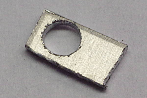
Here is the final sigma.
I filed the outer circular portion of it, and gently sanded its front and back surfaces
solely to make the part look nicer (cosmetics). If I had made the circular part
more uniform, this would look like an OEM part of the camera.
The thickness of the top portion of the sigma will vary from camera to camera, based
on manufacturing tolerances. The thickness of this aluminum sigma is typical,
and I’ve seen thicker.
As the final step, sand the top edge of the sigma with very fine sandpaper to make
it mirror-smooth. Doing so will minimize wear on the back of the rack.
Don’t forget to apply a little grease to the rack.
|
 |
In this photo, the film-advance is at the end of its stroke. At this point, an unbraced rack
would be meshing the poorest with the pinion. But in this photo, they are still meshing at nearly 100%.
The three teeth marked by arrows had been deformed. After repairing them,
the advance feels fine.
You can see a bit of the sigma to the left of the end-plate. This was a good use of one hour of my time.
I suspect that this sigma is a good candidate for 3D printing.
If you do so successfully, please send me the STL file and I’ll add it to this page.
Due to camera-to-camera variation, the STL file would need to have a little excess material
along the top of the sigma which would be sanded down to match each camera.
|
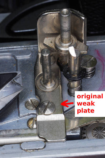
Supporting the Lower Teeth with a Stronger Plate
As described above, the lower teeth in the rack can be in as bad condition as the upper teeth.
There are two reasons for this common failure:
- The rack is inadequately supported from overhead. The thin and narrow plate supporting the
rack flexes when under the high force of cocking the shutter, reducing the mesh and
bending the upper portion of the teeth. This section describes how this design-defect
can be repaired by replacing the original weak plate with a stronger plate.
- Due to camera-to-camera variation in manufacturing, the mesh in some cameras is
substantially under 100% even when under no force. The repair for this defect is
described in the next section, Expanding the Rack.
 |
The original plate is 0.8 mm thick. Your new plate should be made out of steel
that is 1.0 to 1.15 mm thick, preferably at least 1.1 mm. I have found that a thickness
of 45 mils (1.14 mm) works well.
This range of thicknesses of steel can be found in old computers and at hardware stores.
You can wander around a hardware store carrying a magnet (to verify that material is steel) and a micrometer.
Look at products using sheet steel, such as electrical boxes (as pictured) and for roofing.
You will find something.
|
 |
Here is the original plate in a Retina IIIc.
|
 |
In the Retina IIc, the back of the plate (front of the camera) has a vertical portion used
to prevent the release button from rotating. You will cut off and re-use this portion.
|
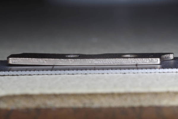 |
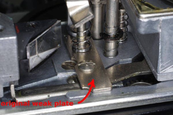
Because they are weak, the original plates
flex upward under the high upward force of the meshing teeth. They flex so much that
they permanently bend, as seen in this photo. Consequently, only the tips of the rack’s teeth
mesh with the pinion in the body, deforming them and eventually stripping them.
This flimsy plate must be replaced with a stronger plate.
|
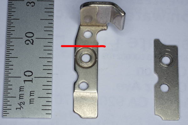 |
For the Retina IIc, Ib, and the second version of the IIIC (big-C),
you will need to cut the original plate at the red horizontal line,
and re-install the upper portion (as pictured later).
The plate for the Retina IIc (left) appears to be stronger than the one for the IIIc (right).
But I’ve observed it flexing upwards under the high back-force on the rack,
so even it is not strong enough. In fact, the lower teeth for this camera were
deformed rather badly, proving that this plate is too weak.
|
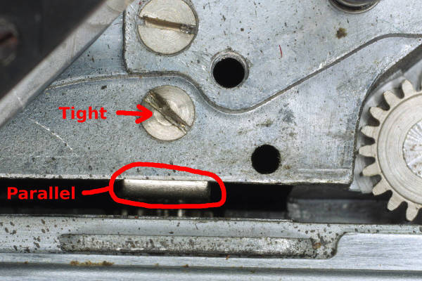 |
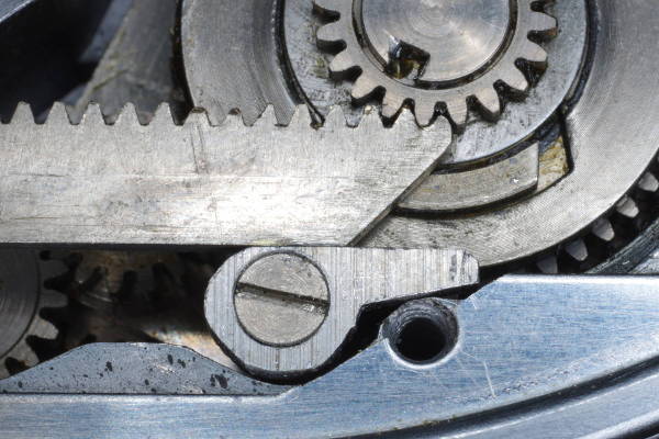
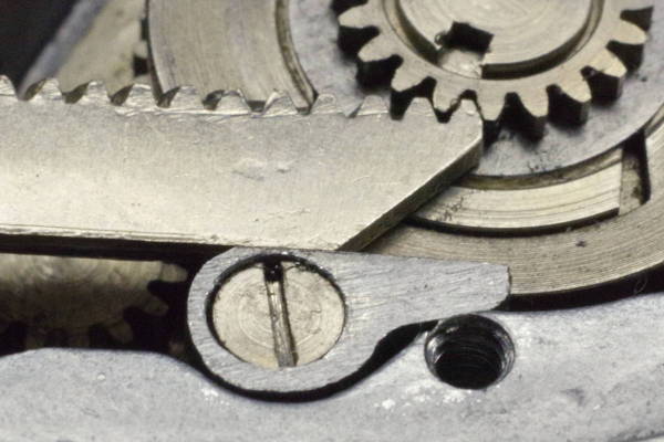
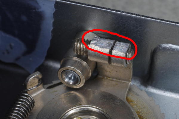
Make sure that this screw is tight! It holds the fore-aft support for the body-pinion.
That support is circled in red. And make sure the support is parallel to the body-casting.
|
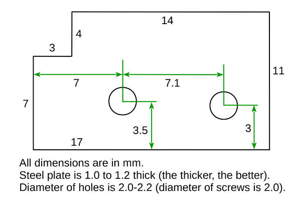 |
Here is the layout of the stronger plate that you will make. This drawing is not to scale, so don’t use it as a template.
After drilling one hole, you can accurately place the second
hole by using the original plate as a template. I suggest drilling the left hole first,
as its position relative to the left edge must be accurate.
Then put the original plate on top of this new plate, place a screw through the
corresponding hole in both, which will keep the plates aligned,
and then start your drill-bit in the second hole, thus positioning it perfectly.
The 3-by-4 mm cut-out at the upper-left leaves room for the counter-advance-tab at the
left end of the rack. The 4 mm is a bit too much; you can get by with 3.5 mm in many cameras,
resulting in a slightly stronger plate. File it a bit if 3.5 mm isn’t quite enough.
|
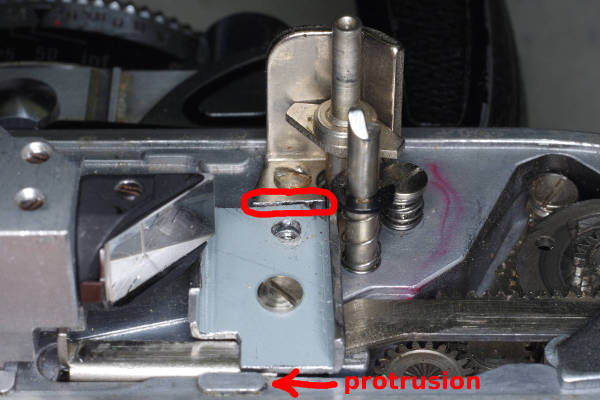 |
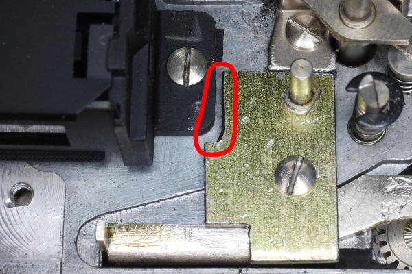
This photo shows where the original plate was cut (circled in red), allowing its
vertical portion to be re-installed in the camera as seen here. Also, the need to avoid the protrusion
(at the bottom of the photo)
present in some cameras is the reason the plate is slightly shorter than the original plate.
The extra length added no extra strength, so shortening the plate is harmless.
This particular plate has ribs on both sides. That’s because the original sheet
metal had 90-degree bends there, and I knew that ribs can only strengthen the plate.
But take care that rib(s) fit under the RF assembly and don’t interfere with
the frame-counter lever in the top-cover.
|
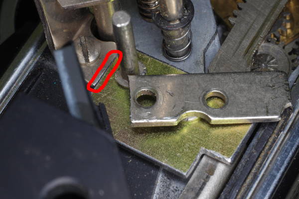 |
Here is the second version of the Retina IIIC (big-C). Like the IIc,
the vertical part of the plate must be cut off and reinstalled separately.
For almost all cameras with these racks, the dimensions given in the drawing (17x11 mm) will fit.
The exception is the Retina Ib: A 1.5x6.5 mm notch must be cut in a corner of the plate
to make room for the viewfinder (pictured later in this article).
|
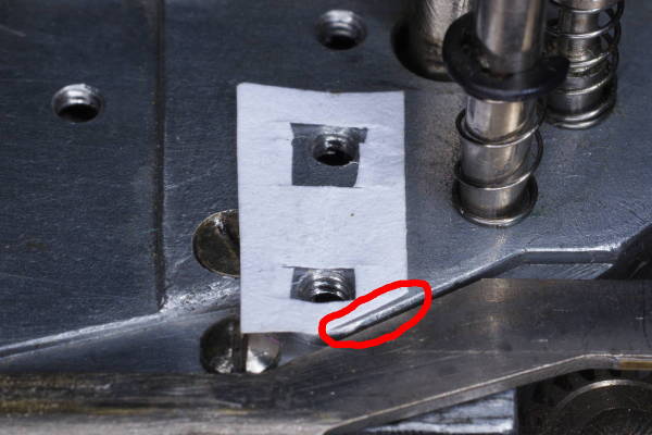 |
The original plate might have had a tiny washer under it. That is a shim that is
0.1 mm (4 mils) thick. Do not re-install it. If the return movement of the rack is stiff,
then cut a shim out of material that is about 0.05 mm (2 mils) thick, such as
magazine paper or a candy-bar wrapper.
Install the plate and test the advance. If its return stroke is still stiff, then cut a shim
out of material that is about 0.1 mm (4 mils) thick, such as the cover of a magazine
or copier-paper (pictured). For both 2- and 4-mil thicknesses, measure the thickness of your material with
a micrometer. Copier-paper in the USA is about 3.7 mils thick. Two different magazines I measured had
thicknesses of 2- and 4-mils for interior sheets and covers, respectively.
The reason to use a new
shim instead of the original is that the tall post at the back of the plate did not originally
have a shim under it, angling the plate slightly, raising the support and causing teeth to mesh less.
Note that the lower right corner of the shim has been cut off (circled in red) to avoid
getting tangled in the rack.
|
 |
This is a view of the counter-lever inside the top-cover of a IIIc, which is upside-down.
The set-screw assembly is very close to the plate, and because your new plate is thicker,
this assembly might rub the top of the new plate, causing it to not retract,
causing the frame counter to advance only once and thereafter be inoperative.
If that happens, loosen the securing screw marked with the red arrow and slide the assembly upward
(downward in this photo) by about 0.5 mm to ensure it will not touch the plate.
Inside the camera, this assembly must be high enough to clear the plate, and low enough that the
frame-counter tab at the end of the rack will touch the horizontal set-screw.
|
 |
The Retina Ib (and probably IIc) lack the height adjuster shown above.
If the counter-lever rubs on the plate, you must grind a little metal from the tip of the lever
as shown here circled in red. This problem often occurs with 1.14 mm (45 mil) plates.
|
 |
This plate was made from the electrical box pictured at the beginning of this section.
Its metal is 1.14 mm thick (45 mils).
The film advance lever is almost at its maximum position, so you can see the frame-counter tab
in the 3x4 mm cut-out in the lower-left corner of the plate.
|
 |
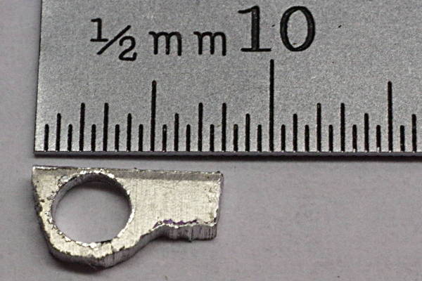
This plate for the Retina Ib has a 1.5 mm by 6.5 mm area cut out of its upper left corner
to accommodate the viewfinder.
Due to the high upward force it endures, I suggest that you not tighten the screw very hard
that holds down the plate. High tightening force plus high upward cocking force might cause the
aluminum alloy threads in the body to strip. Instead, tighten the screw normally after applying blue (medium strength)
thread-locker to prevent it from loosening.
These replacement plates are thicker and wider than the original plate, making them stronger.
Under careful examination of a stronger plate while cocking, I see only a hint of flexing, so its flexing is insignificant.
Hence, the rack will last longer because due to improved mesh. But the mesh of the lower
teeth is still often insufficient to prevent the rack from stripping, especially for the
leftmost teeth which endure the highest cocking force. Expanding the rack cures that problem.
|
Expanding the Rack
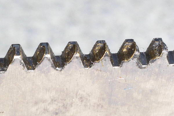 |
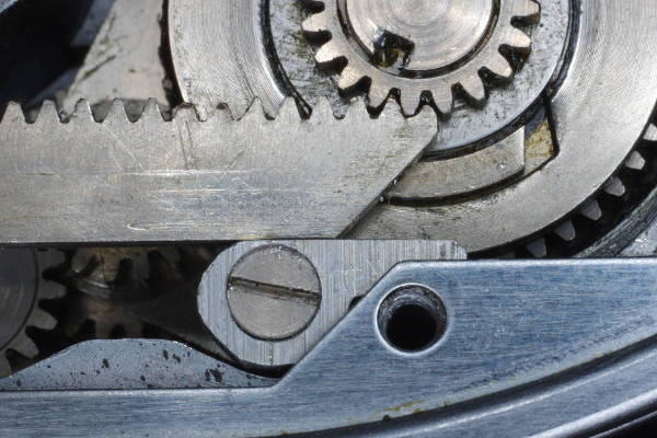
This photo of lower teeth reveals why you will often need to employ the final method of preventing
stripping. The positions of the wear-steps in these lower teeth show that the rack’s teeth
are meshing with the pinion at about 75% of a tooth’s height, and then the top plate flexes
upward some due to the high back-force on the rack, creating a rounded step about halfway down the left side of each tooth.
I verified this assessment of mesh by inking the lower teeth with a felt-tip pen, cocking and
firing a few times, and then examining the ink in a 20X loupe. If the meshing is under about
85%, I think you should improve it. And especially if you repaired a stripped tooth,
which shortens it, you will want mesh to be nearly 100%.
Note that 100% mesh is not possible due to the shape of the teeth. I estimate that the maximum
possible mesh is 95-97%.
In this photo, note that about 20% of the flank of each tooth has no wear. This uneven wear occurred because
the pinion in the body is not perfectly aligned with the rack, which is a manufacturing defect in this camera.
I suggest disassembling such a camera to determine the cause of such misalignment and try to repair it.
I was able to repair the misalignment in this camera by placing a 0.1 mm-thick shim-washer behind the
pinion that is driven by the lower teeth of the rack.
Installing a stronger plate (as described above) will eliminate plate-flexing,
but how can you improve the mesh? Increasing mesh requires that you lower
the teeth by expanding (stretching) the metal above them. But how?
|
 |
Because brass is malleable, you can tap the metal above the teeth in several places
as shown by using a hammer and rod on an anvil, expanding the metal, and thus pushing the teeth away from the top of the rack.
Tap gently and uniformly across the metal. Tap both sides of the rack (front and back)
to avoid creating an arc in the sheet metal above the teeth.
I recommend the following procedure:
- Install a strong plate in the camera as described previously in this article.
- Measure mesh across the rack by inking the valleys between teeth with a felt-tip pen, firing a few times,
and examining the teeth in a loupe.
- Knowing that a tooth is 0.75 mm tall, you can estimate how much the teeth in the right third
of the rack are short of full mesh. The left teeth will mesh less because they see high cocking-force,
but teeth in the right third will determine how much to expand the rack.
- Expand the rack by perhaps 2/3 of the shortfall you measured above.
- Put the rack back in the camera, fire a few times, and re-measure mesh by examining ink on teeth.
- Repeat as necessary to achieve nearly full mesh in the right third.
|
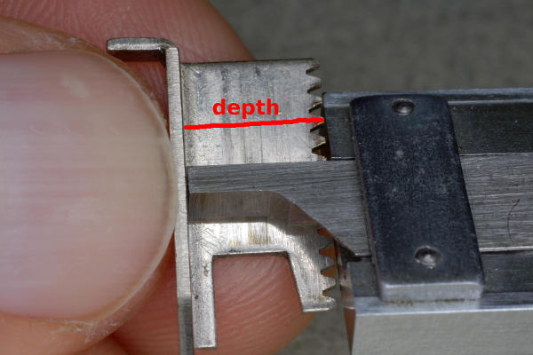 |
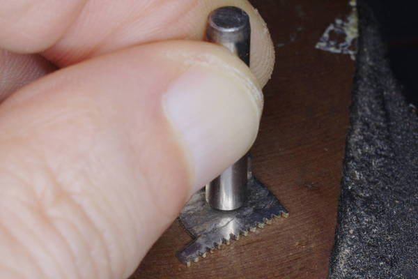
When you expand the rack, measure the depth from under-the-top-of-rack to tips-of-teeth
using the depth-rod in your micrometer, as shown here. Measure at the left, center,
and right ends of the lower teeth to ensure that you are expanding the metal uniformly.
My initial measurements of multiple racks were 7.52-7.54 mm (296-297 mils);
your initial measurements should be very close to these.
Some racks need little or no expansion because right-third mesh is already close to 100%.
But due to variations in manufacturing of the camera bodies, other racks need much more expansion.
|
 |
This was my mistake. I expanded the metal by .25 mm in one pass, which was too much.
|
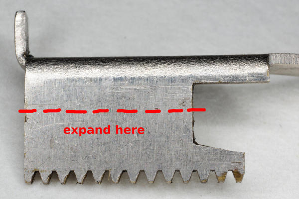 |
I discovered the hard way that the metal near the top of the rack should not be expanded,
because it’s difficult to expand the metal perfectly uniformly, so expanding metal
near the top will warp the top, causing it to bind under the plate. Some of the photos here
show that I expanded metal above the red dashed line, but that was before I learned
this lesson: Expand metal only below the red line.
After expanding the rack so that the right teeth mesh at nearly 100%, you will
probably find that the left teeth, which endure the highest cocking force,
mesh less because the high force separates rack and pinion some, despite the stronger plate.
But due to this high force they endure, these are the very teeth that need full mesh.
The solution is to expand the rack more at the left end than at the right. My most recent project
required 0.2 mm (8 mils) more mesh at the right end, and 0.3 mm (12 mils) more
at the left. From my experience, numbers on the order of 0.2 mm on the right
and 0.3 or 0.4 mm on the left are typical. Yet, some cameras need no expansion on the right,
so don’t expand without first measuring.
You can expand the left more by staying closer to the left teeth when tapping.
But take care to not hit the teeth!
|
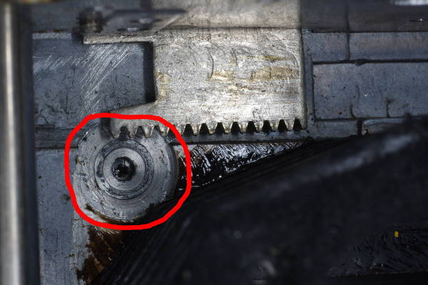 |
Here is the cause of wearing/stripping of lower teeth. On this Retina IIIc,
the folding assembly has been removed, so you are looking at the inside of the
body casting, with the bellows at the lower-right.
Circled in red is a circular feature milled into the casting;
its center-hole holds the shaft of the pinion. The problem is
that the position of this hole is not always accurate; sometimes it is slightly too
low, causing incomplete meshing of teeth, with the consequent failure of the rack.
|
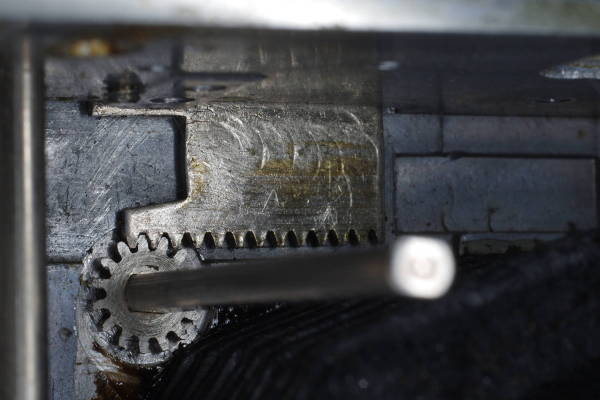 |
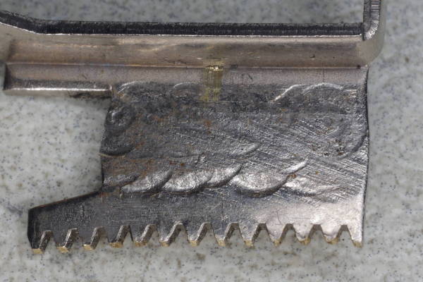
You can see the curved marks on this rack where I expanded it by almost 0.2 mm (7 mils).
It meshes well now. If you plan to disassemble the camera this far, then this would be
a good time to expand the rack because you can easily see how completely it meshes.
But you should still measure the mesh of the left teeth when under high cocking-force
using a felt-tip pen, determining whether you should expand the left side (right side in this photo).
This is the camera with the 20% pinion-misalignment mentioned above.
The cause is that the circular feature in the casting was milled too deep.
My solution was to put a 0.1 mm (4 mil) shim-washer behind the pinion,
pushing the pinion toward the front of the camera where it will hopefully
not miss a portion of the rack’s teeth.
|
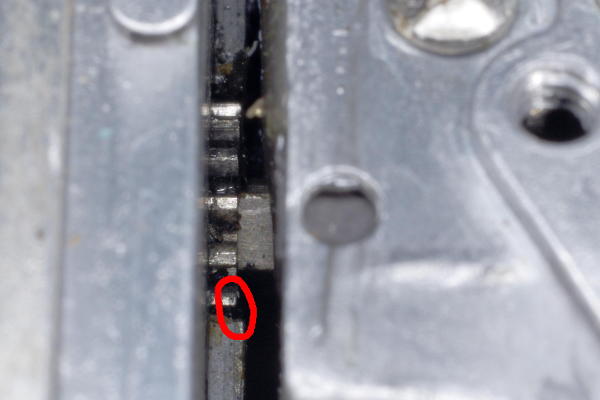 |
Here is photo looking down at the top of a different camera with the same problem:
As the red circle reveals, the pinion is a little too far to the left due to the milling-error mentioned above,
so the right portion of the rack’s lower teeth will be untouched, thus not utilizing all the strength of each tooth.
I estimate that this pinion will need a 0.2 mm (8 mil) shim-washer to align it well with the rack.
Despite having good mesh vertically, the rack in this camera stripped, and I suspect the reasons were:
(1) the horizontal-shift you see here,
(2) a flimsy support-plate, and
(3) needlessly high cocking-force due to the M-sync mechanism in the shutter.
This article explains how to prevent the first two problems, and the article referenced next solves the third.
|
SUGGESTION: Remove M-sync from the shutter.
The two stronger supports described above, plus expanding the rack,
keep both ends of the rack in full mesh, but that does not eliminate the
fact that those small brass teeth endure too much force, and I wonder whether they
will gradually deform despite being in full mesh. M-sync is not needed, and removing it reduces the maximum cocking
force substantially, which could make the difference between preserving versus
stripping your rack.
Here’s how to remove M-sync.
If the rack is damaged or stripped, here is a way to repair it.