Due to poor design, the shutter-cocking racks in the later folding Retina cameras (models Ib/IIc/IIIc/IIIC) are prone to stripping.
Each time you shoot a roll, the rack is damaged a little in the form of bent teeth. Eventually, the rack and pinion
jump a tooth, and the rack is stripped.
The good news is that a damaged or stripped rack can be repaired, and will then function smoothly and reliably.
But after repairing the rack, its support in the camera must be strengthened. Also, it is strongly advisable
to reduce cocking-force by removing M-sync from the shutter, decreasing strain on the rack.
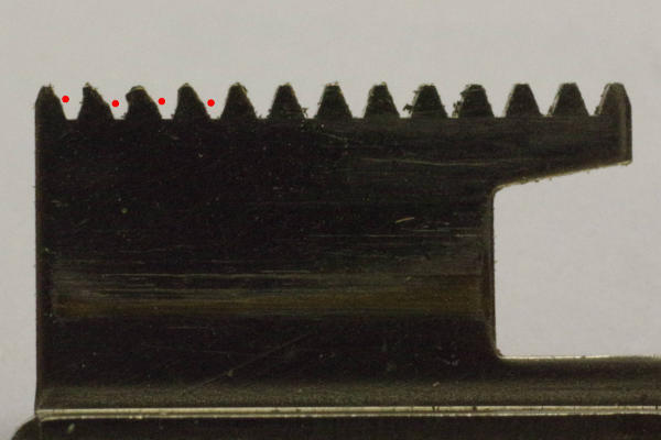 |
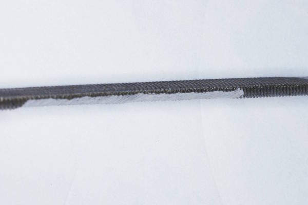
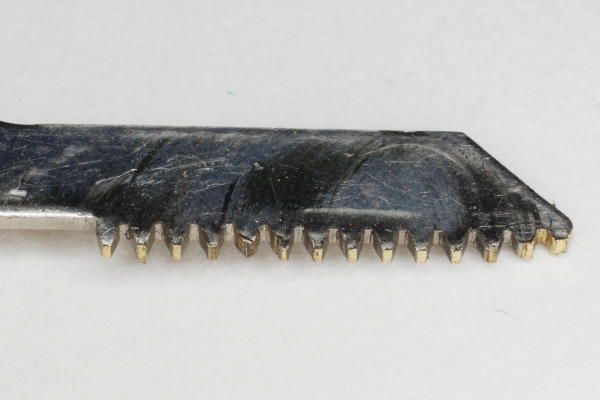
The rack has teeth at both ends, and this is an example of typical damage one sees
on the lower teeth. High cocking-force causes the rack to separate from its pinion some,
so the steel pinion digs into the rack’s teeth partway up each tooth, cutting a step
into each tooth where cocking-force is high. The red dots in this photo show these steps
in these teeth.
|
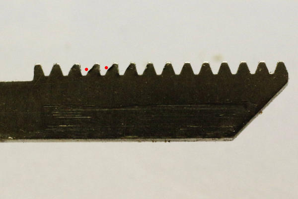 |
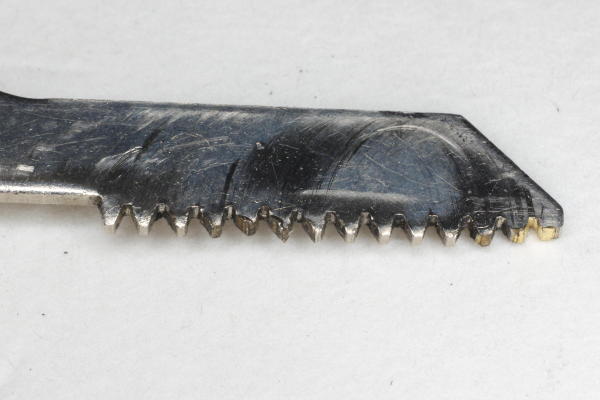
The upper teeth sustain the same kind of damage, but usually a little worse,
so the upper teeth usually strip first. The red dots mark the steps, and you can see
that those teeth are leaning (bending) to the right. The tips of such teeth eventually
bend over completely, yielding the dreaded stripped rack.
|
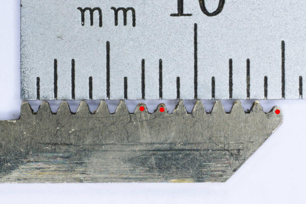 |
This rack was stripped in the middle and at its right end, and was then repaired.
But metal was lost on the stripped teeth (marked with red dots), so they are now
shorter than the others. To use this rack, it is essential that these teeth engage
fully with the pinion, which is why you must strengthen the rack’s support,
in addition to repairing the rack. Once supported properly, this rack cocks the
shutter smoothly and reliably — the shorter teeth are not a problem when
rack and pinion are fully meshed.
I have tried several techniques of repairing racks, and this article describes
the best I have found so far.
|
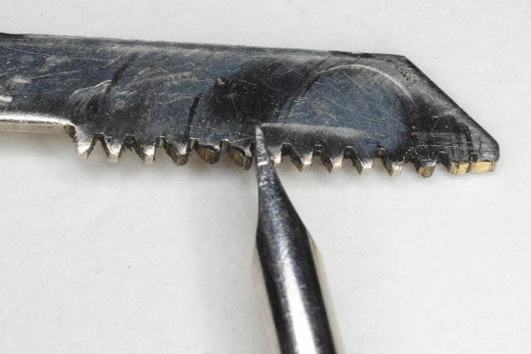 |
Step 1: Put the rack in a vise, and use a screwdriver to straighten
each leaning tooth some. Use the largest screwdriver available whose tip is narrow enough
to fit in the bottom of the valley between teeth.
You will need to press down hard while moving the screwdriver sideways to straighten the tooth.
|
 |
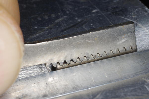
In the photo above, notice that the right two teeth are partly sheared off,
filling the valley between them. I made the slitting file shown here to fix
individual teeth. This was a normal, thin file, but I used a Dremel to grind the
teeth off one side of the file. This file allows you to file a tooth on one
side while not affecting its neighboring tooth. I used it to file the material out of the valley.
This leads us to step 2.
Step 2: File material out of valleys as necessary.
It is tempting to use this tool to remove the part of a tooth that is leaning
to the right. Don’t. The next step solves that problem.
|
 |
This is the result of the prior two steps. But the teeth are still leaning some.
|
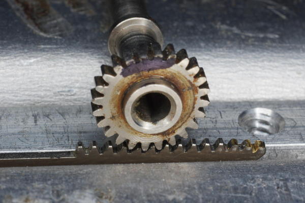 |
Step 3A: Fasten the rack in a vise between pieces of smooth metal, place a steel pinion over the teeth as shown,
hold the pinion level, and tap the pinion with a hammer. I suggest starting in an area with
good (non-deformed) teeth, and tapping and rolling the pinion a little. Then move over one
tooth, and tap and roll again.
Tap gently. Re-forming brass teeth only requires gentle blows with the hammer.
Continue until all teeth have been covered. The teeth on the
ends require that the rack be centered over them.
This tap-and-roll method causes the good teeth to determine
the locations of the valleys.
The steel pinion shown here is the gear that drives the curved rack by the shutter in a Retina folder.
You could probably use the curved rack itself for this purpose as well.
Brass is malleable, so the teeth will be molded to the pinion’s teeth.
It is important that you mark a portion of the pinion, and only hammer in the marked area,
because those teeth on the pinion will be flattened some from the hammer blows.
In this photo, you see that the top portion of the pinion is marked black.
|
 |
Step 3B: Another option is to fasten the rack in a vise as above, but place the steel rack
from the top of a Retina Reflex over it, and hammer on that rack, molding the brass teeth to the
shape of the steel Reflex rack. The Reflex rack is a little thicker
(1.0 vs 0.8 mm), making it easier to completely cover your rack with the Reflex rack.
You will need to hit this steel rack harder than you did with the pinion above,
because the force is distributed among all of the teeth.
|
 |
Here is the result of steps 3A and 3B (I did both).
This rack is useable again. This ruined rack was rescued.
As a resulting a re-forming brass, a few teeth might be slightly taller than normal.
I suggest gently moving the entire rack over a flat file to remove such peaks.
If a tooth is still leaning enough to cause binding in the camera, then I suggest
repeating step 3 over that tooth. If step 3 does not remove the lean,
then its leaning side can be brought back to the normal angle either by
(1) hitting its leaning flank with a thin steel tool, or (2) using the slit-file described above.
But be gentle with that file. You will be surprised at how much brass can be
removed in one stroke of the file. It makes you appreciate how soft brass is.
It makes you realize that these brass racks should have been made out of steel.
|
After repairing the rack, you