The Retina Automatic III has most of the features of the Retina IIS (which is a IIIS with a non-interchangeable Xenar).
Both are well made and attractive, having sharp four-element Xenar lenses, very good VF/RF, manual control of speeds and apertures,
built-in meter, and flash-sync. But most people avoid the Automatic III because it’s unreliable — most examples are inoperative.
Also, its auto-exposure mechanism makes the camera too noisy due to a crude escapement at the back of the shutter,
and the firing lever for the shutter requires much force to press, increasing muscle-shake.
Those of us who are getting older already have too much shake; we don’t need more.
This article describes a modification that (1) removes and bypasses the auto-exposure mechanism,
(2) makes the camera quiet, and (3) makes it much easier to fire.
After these changes, the Automatic III will be identical to the IIS except for the
lack of slow speeds, self-timer, M-sync, and LVS (representing an advantage over the IIS).
In fact, the lack of LVS makes this modified camera easier to use than the IIS, IIIS, the Reflex models, and the IIc/IIIc/Ib folders.
On this camera, you directly set the shutter-speed and f-stop. The meter suggests an f-stop based on your shutter-speed,
which you might wish to ignore if the selenium cell is weak.
If you want to change those settings without changing exposure (maintaining constant EV), you simply hold both rings
and move them in tandem. Focusing is easier than almost all other Retinas because you hold a knurled ring instead of a tab.
The front-release makes the camera easier to handle than the common top-release because you can rest the camera on the
remaining three fingers, thumb in back, forefinger on the release. That’s a more comfortable
position than a top-release camera; try it. Having the viewfinder on the left side means that a left-eyed person
can use the camera without his nose bumping his thumb.
The Retina IIF is an upscale model of the Automatic III, but the IIF suffers from a centered viewfinder, so nose bumps thumb,
and its RF-base is 24 mm versus 36 mm in the Automatic III, making focusing noticably more difficult.
No other Retina is as convenient and well thought-out as the modified Automatic III.
No other Retina has such good ergonomics.
Because it has the best ergonomics and is built with traditional Retina-quality, I think the Automatic III
is among the most desirable Retinas — but only if it’s been modified.
The Retina Automatic III was manufactured in two major variants. The second version has a longer
meter cell than the first, making the variant obvious. I have found that meter cells in first
version cameras are usually dead, while most meter cells in the second version are alive and
appear to be close to accurate. Also, the second-version cells are more sensitive.
Evidently, Kodak used a better cell in the second version.
In addition, the second version added the annoying frame-1-lock feature found in the folding models
that cause the frame-advance to lock when the frame-counter reaches 1. Kodak foolishly added this expense
at a time of intense price-competition with Japan. Also, based on the serial numbers I’ve seen,
it appears that late in production Kodak changed the advance-lever casting and put a plastic tab on it.
In all variants, the rewind shaft is made of plastic, and the rewind knob cannot be raised for rewinding,
making rewinding significantly slower than the folders. To my surprise, this raiseable-knob feature was also
removed from the IIIS and IIS. The rewind knob was made thicker presumably in a feeble attempt
to make rewinding less frustrating.
My overall assessment of this camera is that it is well designed and well made, with the glaring
exception of the automatic mechanism which is overly complex for what it does and which makes
the advance lever too hard to push. The modifications below fix these flaws by removing
that mis-engineered mechanism.
This page is intended for experienced camera repairmen, so it does not explain how to perform
common chores such as peeling leatherette. As an aside:
Be careful when cleaning the focus-scale of this camera. I cleaned one with Fantastik, which
to my amazement dissolved the paint on the focus-scale on the focusing ring, removing some of its numbers.
Even water rubbed off some paint! Kodak must have used poor paint on the focus-scale
because I’ve never had this problem on any other kind of camera. All other paint
on this camera is fine.
 |
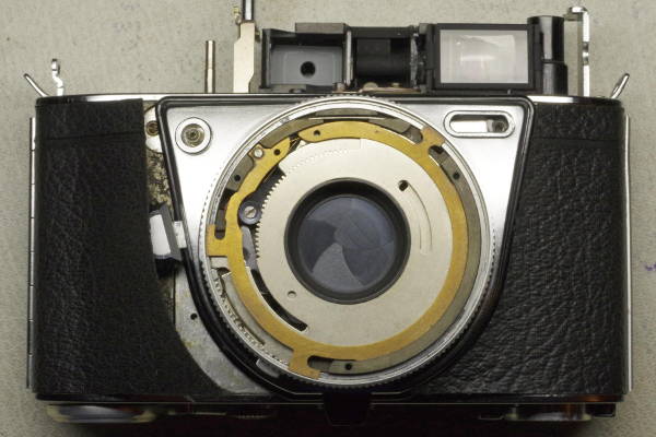
You first must remove the top of the camera. Here is the procedure:
- While blocking the tines of the rewind shaft with a strong flat object (I use the handle of my tweezers),
unscrew the rewind knob by hand. Do not put a tool on the pin-face screw on the rewind knob.
When the rewind knob is about to come off, turn the camera upside-down and unscrew it completely.
There is always a spacer and sometimes a washer on the screw, and you want them to stay on the screw
(which is on the rewind knob), and not fall into the camera.
- Remove the two screws that were under the rewind knob.
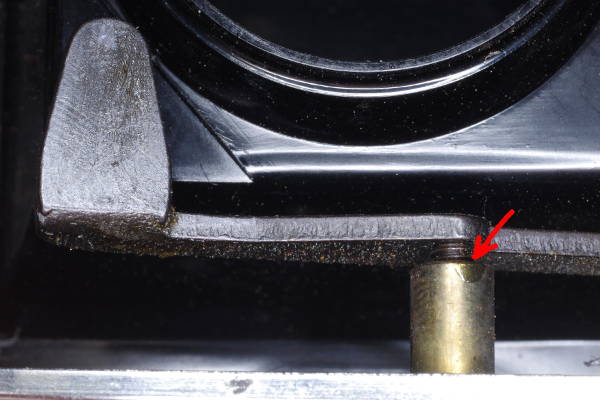
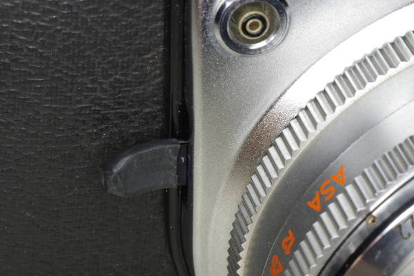
- Remove the screw by the strap-lug on the other side of the camera, pictured here.
- Lift the top off.
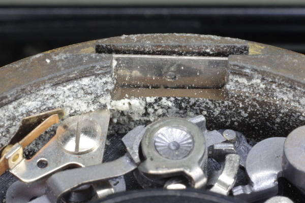
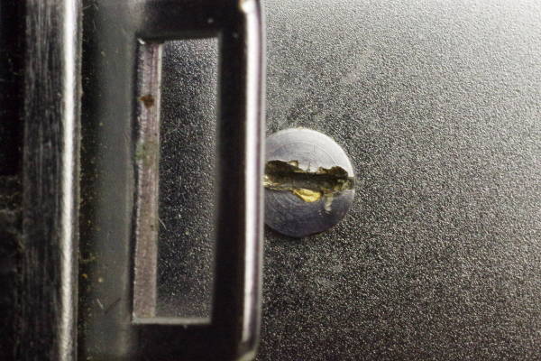
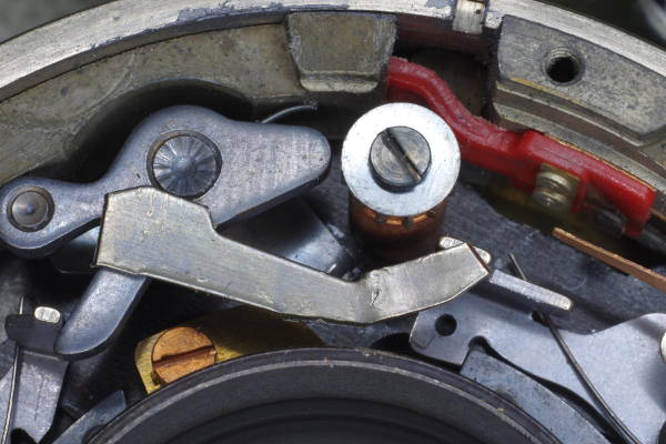
I have seen too many cameras with damage on and around screwheads, such as this example. When I see this, I say,
“Uh oh, a slob has mangled in here.” Don’t be that slob.
First practice on a junker until you are skillful and have learned to be careful.
|
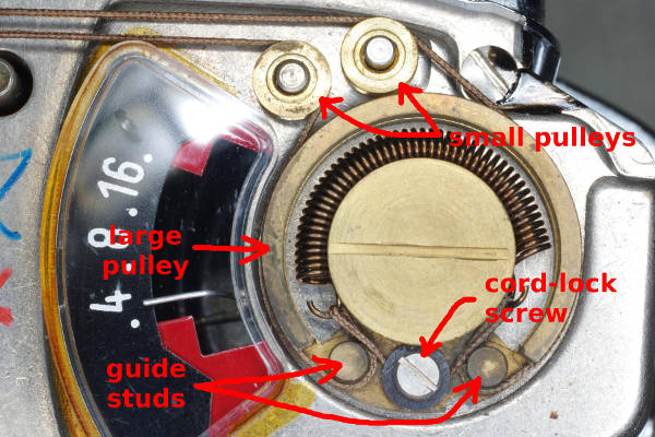 |
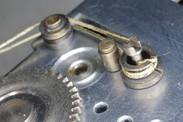
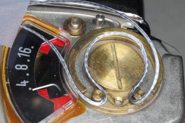
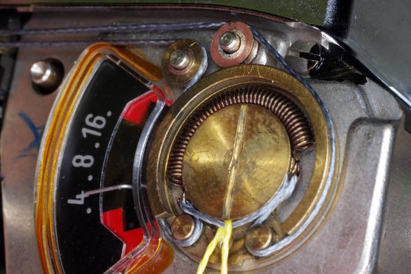
If the meter is dead, you can cut the cord on the meter, and remove the spring and
the two small pulleys at the top of this photo.
But if the meter is alive and you wish to use it, use a felt-tip pen to mark the cord by the
cord-lock screw. You will use this mark to maintain the original meter calibration upon re-assembly.
However, I suggest replacing the original cord (made of cotton or somesuch) with braided
fishing line, which is considerably stronger and probably not subject to deterioration.
Remove the cord-lock screw, and unstring the cord. Remove the two small pulleys.
|
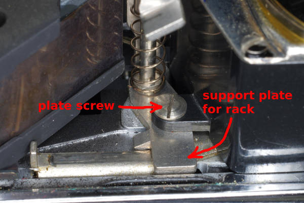 |
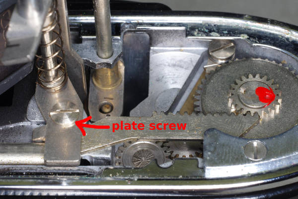
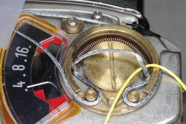
This “plate screw” holds down both one side of the meter and the support plate
for the rack. Remove it. Unscrew the other screw (by the strap lug) securing the other side
of the meter, but leave it in place as it is trapped by the meter housing. Pull out the meter.
The camera’s front bezel assembly for the meter/RF/VF consists of a chrome pressing,
a piece of glass, and a plastic decoration
behind the glass. The meter is in one end of the chrome pressing. The pressing hooks to
the body under the meter, and the meter has a plastic lip hooking it to the glass.
Because bezel and meter are thus interlocked,
it’s best to lift out the bezel assembly and meter together by putting two
fingers over the front of the meter (and bezel), your thumb on the back of the meter
(at the back of the camera), and lifting all out together.
|
 |
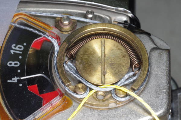
Put the plate screw back in, as shown here. It’s important to support the plate so that
you can cock the shutter without damaging the rack.
Examine the rack and its pinion gear for damaged teeth. They are usually fine.
|
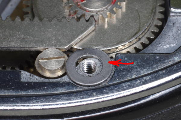 |
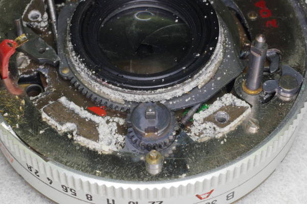
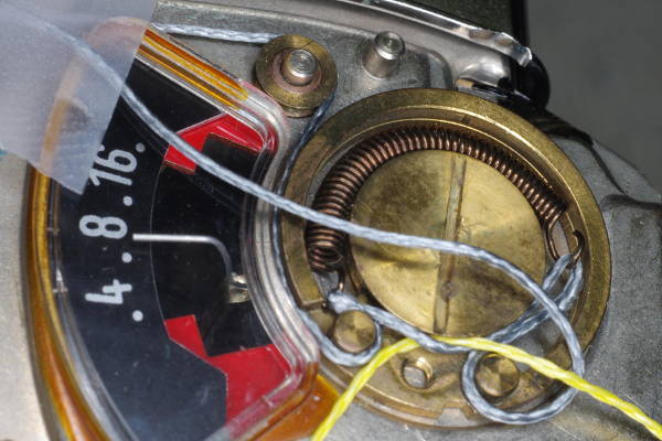
The cocking rack in this camera is not secured properly,
which is a defect in design that can cause racks to bend excessively near the end of the
cocking travel, often causing their teeth to wear or strip. You can fix this problem
by bracing the rack from behind its teeth. In this photo, I have placed a small washer
for the screw securing the right support plate for the rack.
I also bent the flat part of the washer down slightly
so that more of its area would contact the back of the rack.
If the chrome trim-piece lacks a cut-out for a washer here, you will need to
remove some material from the trim-piece using a Dremel.
|
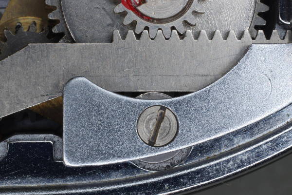 |
The advance lever is fully rotated, putting maximum force on this rack and pinion.
You can see that the washer prevents the rack from flexing away from the drive-gear above it.
Fortunately, the cocking-force in the modified Retina Automatic III is low enough
that bracing its rack like this might not be needed.
However, I strongly suggest bracing racks in all other models of Retinas with this design-defect,
which include the Ib, IIc, IIIc, and IIIC. Here’s how.
|
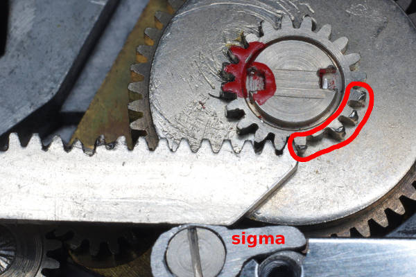 |
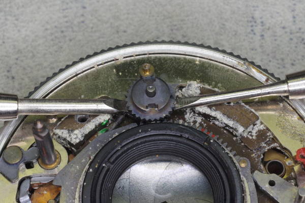
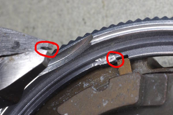
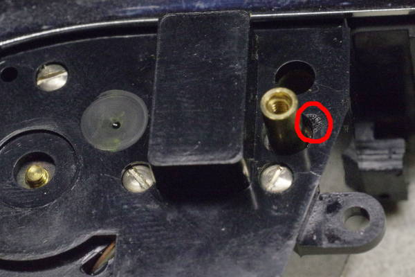
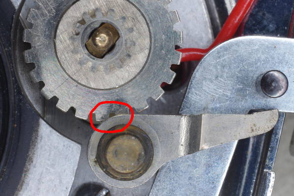
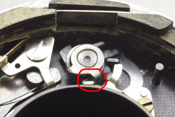
If teeth on the pinion are damaged (red circle), you can avoid them by rotating the pinion 180 degrees.
As seen in this photo, this rotation will use the still-new half of the pinion, avoiding
its damaged half. This trick is suitable for all rack-based Retinas, and it works because
Retina cameras advance and cock in a 180-degree stroke, thus using only half the pinion.
Also, I braced this rack with a sigma (at the bottom of this photo)
because it is a more reliable kind of brace than a washer.
This article explains how to make a sigma.
|
 |
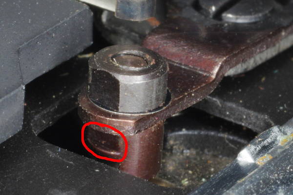
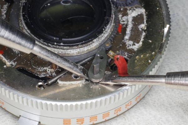
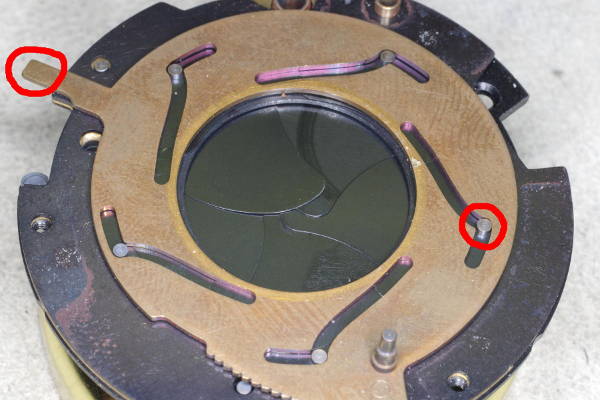
If you remove the rangefinder, you will notice a small plate with a spring-loaded tab, and this
plate-tab combo will be loose because it was secured by the rangefinder’s screws.
Don’t discard it because (1) it raises the RF-assembly to the correct height,
and (2) it covers a “Stop” message in the viewfinder optics.
|
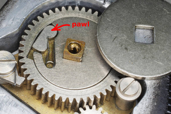 |
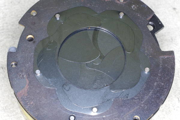
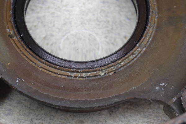
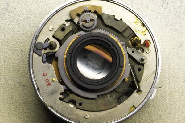
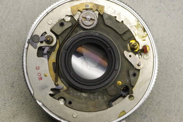
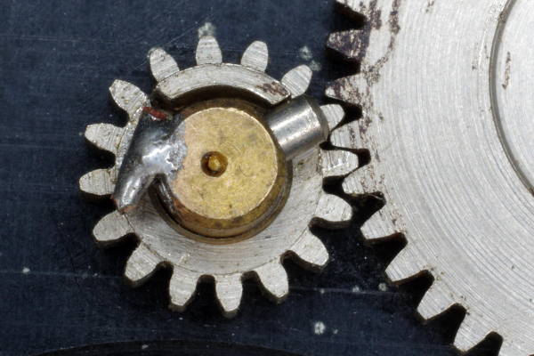
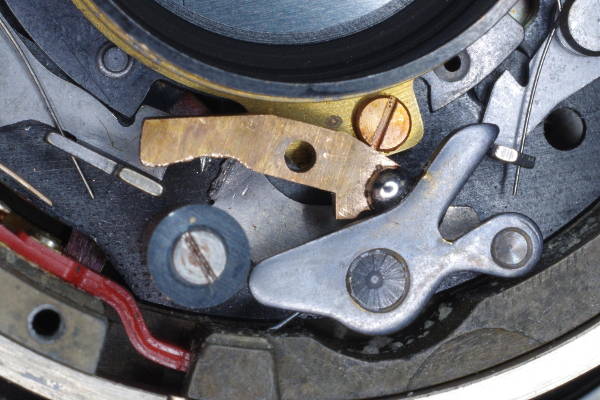
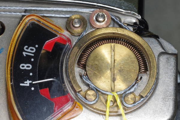
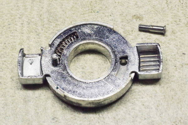
I noticed that the film-advance mechanism was redesigned for the Retina automatic family.
In particular, the one-way catch for the frame-advance is
different from folding Retinas, as shown here.
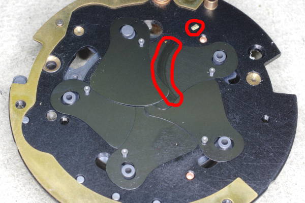
The loose disk on the right covers the new pawl-based mechanism in the middle.
The problem was that grease on these parts was thick enough that the tiny spring
you see pressing on the pawl could not move the pawl into engagement, so the shutter cocked
but the film did not advance. My solution was to wipe off the grease
on these surfaces so the pawl could move freely. Be careful with that
spring. Although it appears large in this photo, it is in fact tiny and
can easily fly away.
This camera has a very low serial number. I examined this mechanism in a later
camera, and it has almost no grease in this area. Kodak learned their lesson.
|
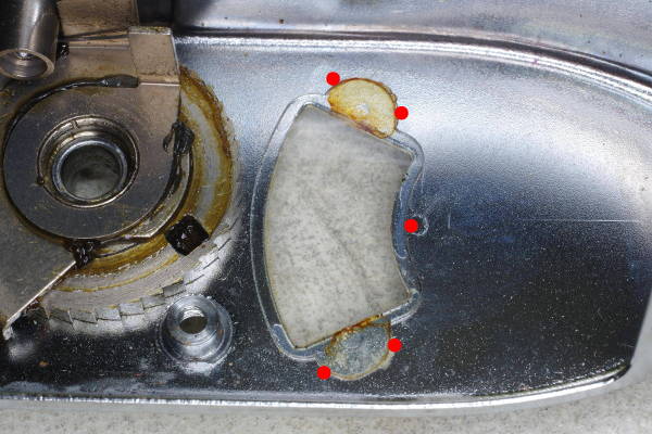 |
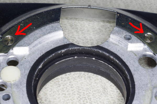
If the meter’s window has not come loose already, it will someday because its glue
has become brittle. I suggest applying a tiny drop of Superglue at the five spots
marked by red dots. The glue will wick into the gap between metal and window,
securing the window. Superglue adheres poorly to chrome, so it mostly attaches
the plastic window to the residual original glue on the chrome. Therefore,
do not clean off the original glue. If there is no residual glue on the chrome,
I suggest using contact cement instead of Superglue.
If this meter window is cracked or missing, you can make a replacement by cutting
a suitable piece from a flat section of common product-packaging. The clear plastic
for such packaging is made out of PET, which works fine for this application. Get
the thickest packaging you can find (generally for larger items).
Glue this replacement window to the chrome using contact cement.
|
 |
The next several steps show you how to remove a lever from the shutter.
The set-screws for the focus ring
are concealed under a decorative ring that’s threaded onto the filter-threads. This ring has no spanner slots;
the spanner slots you see in the photo are for the front lens element.
This decorative ring can be removed with your thumbs, if you’re fortunate. Otherwise, you’ll need to use
a rubber tool on it.
Upon re-assembly, do not tighten this decorative ring. Only screw it on snugly enough that it won’t loosen on its own.
This reason to avoid tightness is that all the force from this ring is transferred to the three
small set-screws shown below; thus, high force can damage the brass ridge against which they press. I have seen such damage.
|
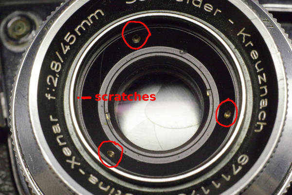 |
After removing the decorative ring, the three set-screws securing the focus ring are visible (circled in red).
- Put a scratch on the ring with the set-screws (marked with a red line)
and a tiny adjacent scratch on the small lip of the focus ring (marked with a red dot).
You will align these upon re-assembly to maintain correct focus calibration.
- Loosen (you don’t need to remove) the set-screws, and remove the focus ring.
- Remove the RF coupling rod.
- Remove the ring with the depth-of-field scale. It is secured by three tiny screws which will
require the smallest screwdriver you have. Take care not to lose these ant-sized screws.
- Remove three screws around the perimeter of the shutter, and the plate holding the helical-assembly
will come off. Note that you need not unscrew the front element of the lens.
- Remove the remaining rings and plates in front of the shutter until the mechanics of the shutter are accessible.
Warning: One of the plates is a rotating disk with gear-teeth on it. Note its position so that,
upon re-assembly, you can maintain its original mesh with the gear that it turns.
|
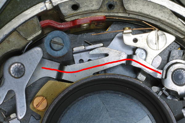 |
Inside the shutter, there is a long lever marked here in red.
Using needle-nose pliars, bend this long lever at its left end
by 90 degrees until it’s pointing up, as seen in the next photo.
|
 |
Repeatedly bend the long lever back and forth at the bottom until it breaks off from metal-fatigue.
|
 |
The long lever is shown here sitting on top of the shutter.
It was broken off at the red circle in this photo.
I had you break off this lever now so it would not press against a tab on the main-cam,
which would rotate a part and ruin your gear-alignment upon reassembly later.
|
 |
Optional: Instead of soldering in the brass pallet as described later, you can solder a section
of this long lever instead. If you choose to do so, you will need to cut the long lever
down to the shape shown here. The metal is soft, and can be cut with a small wire cutter.
I prefer the brass pallet because, in my experience, solder adheres more readily to brass
than steel.
|
 |
Re-attach the front rings and plates to the shutter until it looks like this. At this point
you will modify the body, and will return to the shutter later.
Warning: Be careful to maintain the original alignment of the gear-teeth in this photo.
|
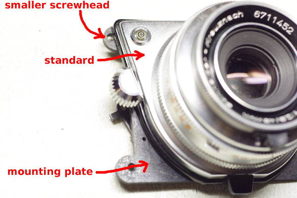 |
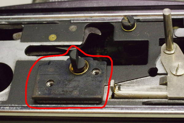
This photo shows what I mean by “mounting plate” and “standard”.
On the body, the mounting plate can be removed by removing four screws, three of which are under the leatherette
near three corners of the chrome standard.
The fourth screw is hidden under the Kodak emblem at the upper right corner of the standard. This emblem is thin
aluminum, and to avoid damaging it, I suggest applying acetone to it
for 5-10 minutes to dissolve the glue under it.
Then push sideways on an edge of the emblem with the sharp tip of a wooden or bamboo skewer.
The emblem will slide sideways and come off.
Here’s a brief article
showing how to neatly remove this emblem.
The upper-left screw has a smaller screwhead than the others to allow it to fit partly under
the black plastic trim. Don’t mix it up with the other screws.
|
 |
After removing the mounting plate from the body, you will need to deal with the meter cord.
If you’re not going to use the meter, simply pull off the cord and discard it.
But if you decided to use the meter, and you wish to use the original cord,
you can tape the cord to the mounting plate to keep it from unspooling.
If you are going to replace the cord with braided fishing line, as I recommend,
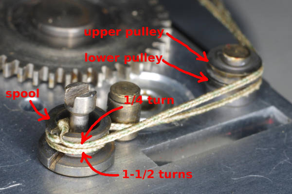
you will need to know how both ends of this cord are strung on the spool.
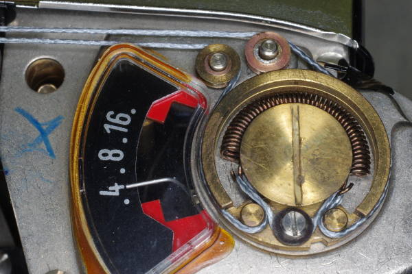
While using a finger at the end of the loop to keep the cord taut and on
the upper and lower pulleys, change the ASA to 10 (its lowest setting) and the
shutter-speed to 500 (its highest setting). At these settings,
the slot in the spool should be facing down (from the camera’s point of view).
The cord should look like this and the next photo. There should be 1/4 turn on end of the cord leading
to the upper pulley, and 1.5 turns on the end leading to the lower pulley.
If there is not 1/4 and 1.5 turns on your spool, then your camera has been tampered with.
|
 |
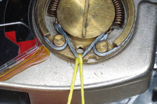
Here is another view of the spool and cord. You can see that the end of the cord leading
to the lower pulley has 1.5 turns.
Each end of the cord has a little knot which keeps it from slipping out of the slot in the spool.
In two of my cameras, I measured the length of the cord as 207 and 208 mm between the knots (excluding the knots themselves).
|
 |
This RF coupling lever is supported by a little screw that is usually loose.
Push the lever up and down to see if there is any play; if so, turn the screw with
tweezers to remove the play. Whether it’s loose or not, I recommend securing this screw with
a small drop of blue (medium strength) thread-locker (Loc-Tite). Take care to not
get any thread-locker into the pivot.
|
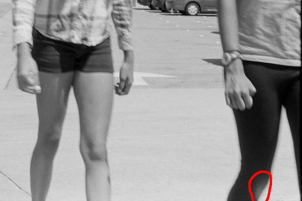 |
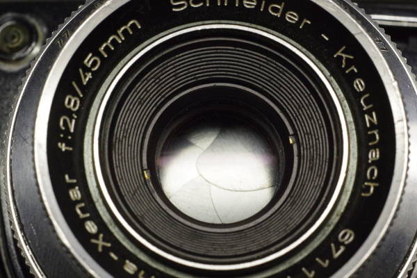
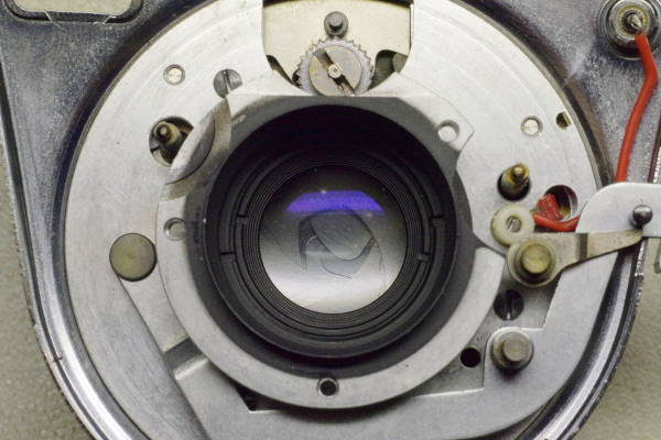
Here’s a crop of a picture taken with a Retina Automatic III.
What caused that flare on the bottom circled in red?
It was caused by what I call “sill flare”.
To understand this, recall that the film window, also termed the “film aperture” or “film gate”,
is the 24-by-36 mm opening that film touches in the back of your camera, delimiting the image-area.
This window has sills on its top and bottom that are a few mm deep,
and light reflecting off these two sills creates the flare you saw.
I know of three ways of eliminating such flare, described
in this article. I have ground these sills down to 45 degree
(or steeper) slopes using a Dremel. Because the shutter assembly is off the camera,
you can more easily make this modification.
|
 |
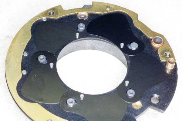
This is the back side of the mounting plate after removal from the body, and removing the cord.
This is a different camera than that above; this one has a black mounting plate.
Later, you will modify the small gear above the lens-opening.
|
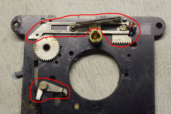 |
Remove the mounting plate from the standard and shutter.
The other side of the mounting plate has some parts on it related to auto exposure. Remove the horizontal slider
at the top. Also remove the lever at the lower left. But it’s riveted on, so you’ll
need to break off both parts of the lever, unless you wish to drill-out the rivet. I slide a screwdriver under
each part of the lever, tilt it upward as far as possible, and then bend the piece back and forth until
it breaks off from metal fatigue.
|
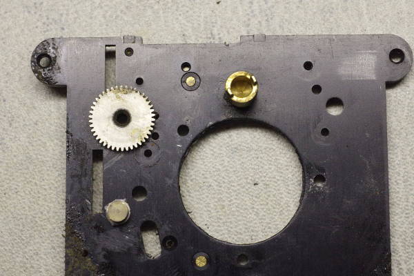 |
Here’s the mounting plate after removal of those parts.
|
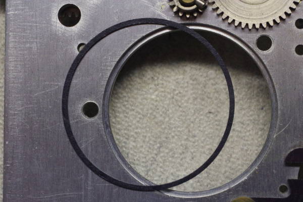 |
Don’t lose this light-blocking washer, if present.
|
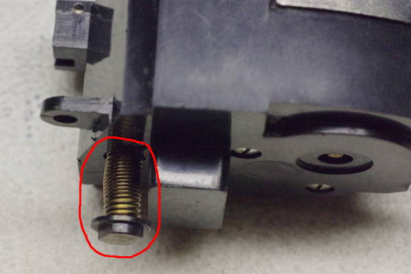 |
The next several steps describe some modifications to the body.
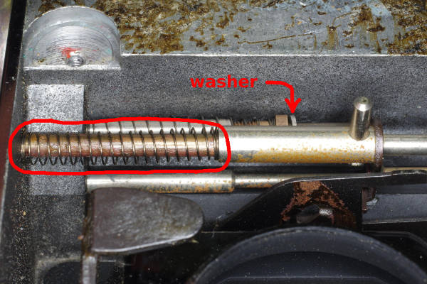
Remove the coiled spring on the bottom of the meter. Save it, because you will use it later
for a different purpose. The black cap below the spring is a screwhead holding
on the spring.
|
 |
Here’s the meter with the spring gone. If you intend to use the meter, you must defeat the trapped-needle
mechanism inside the meter by pushing the shaft fully in, and locking it with a drop of Superglue
applied at the opening, as indicated by the red circle.
|
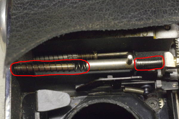 |
You see three horizontal coil springs in this photo that are on shafts.
Remove the two that are circled in red.
|
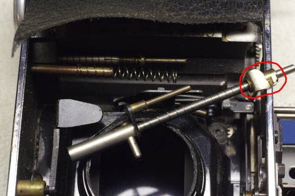 |
Doing so will require that you remove this shaft. Also remove and discard the sliding
piece on the right end of this shaft (circled in red).
|
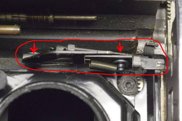 |
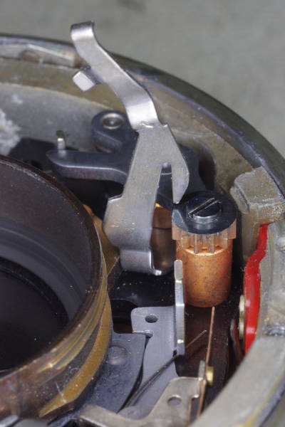
Here are some levers involved with the auto mechanism.
The following steps will keep them out of the way.
Do not remove the spring connecting these levers,
as it will help keep the lower lever where you want it.
- The levers tend to spring up, so press the upper lever down (toward the back of the camera),
causing both levers to move down.
The plate screw you inserted several steps ago will stop their movement at a position where the levers
will not cause trouble. Continue pressing down while performing the next step.
- Put a drop of Superglue on the pivots at the two red arrows in this photo.
The left pivot is a thick rivet. Place the drop at the bottom of the rivet
where a lever rotates on it, not at the top of the rivet where it is attached
to the body (wasting glue).
This procedure freezes the levers in that position so they cannot cause trouble.
Furthermore, you will repurpose the frozen upper lever in a few minutes.
|
 |
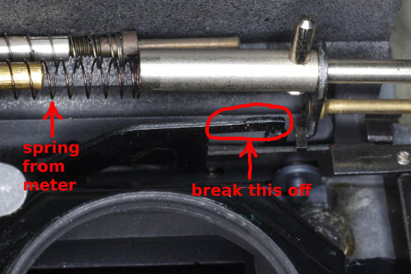
Place the coil spring that you removed from the meter onto the brass shaft at the
left-middle part of this photo (circled in red), and reattach the release shaft as shown.
Some cameras have a washer on the other shaft as shown. If present, be careful
to not let it come off.
|
 |
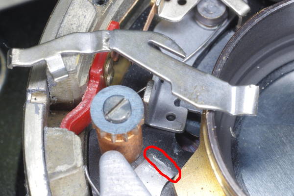
As seen in this photo, the spring from the meter can push the release shaft far to the right,
which will be a constant annoyance while working on the camera.
Here is a way to limit the travel of the release shaft.
Circled in red is a long tab on the upper lever which you glued in place.
Remove this long tab by cutting it off with a small wire cutter.
Its soft steel makes cutting easy. Alternatively, you can
bend it back and forth until it breaks off from metal-fatigue.
|
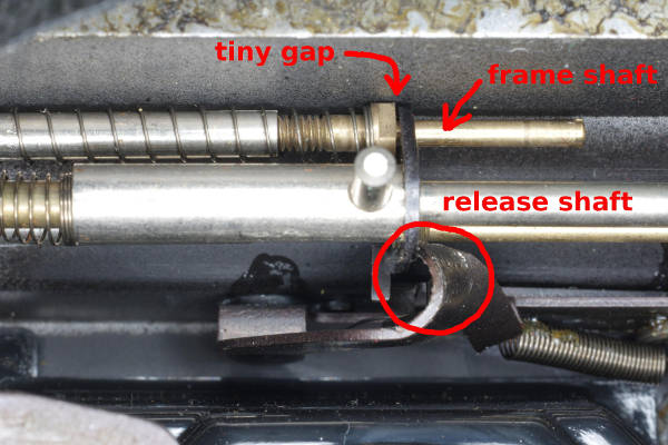 |
After greasing the appropriate spots on these shafts, cycle the advance lever
to advance one frame. For later variants of this camera, you will need to press on the frame-one-lock shaft a little
to unlock the advance. When advancing, you will see the frame shaft in this photo pop upward
(rightward in the photo) by about 2 mm. This is the cocked position of the advance mechanism.
Bend the upper auto-mech lever (which you glued down) so that the slider on the
release-shaft leaves a fraction of a mm gap with the frame shaft, as shown.
|
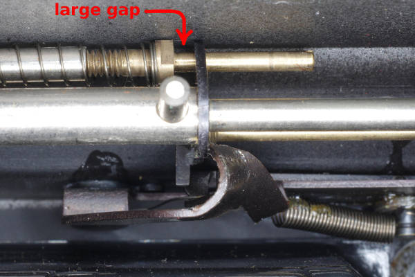 |
After pressing down on the release shaft (to take a picture), the frame shaft
remains down, leaving the large gap as shown. Upon advancing again, you should
see the frame shaft pop upward, leaving the tiny gap.
|
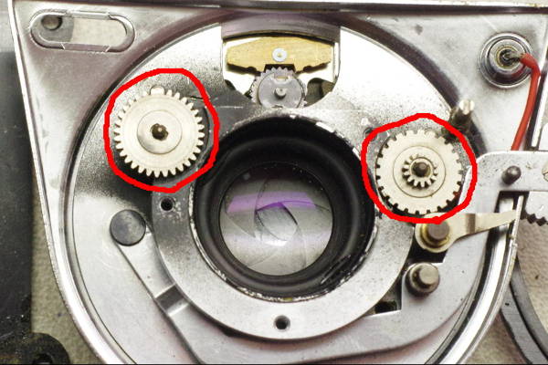 |
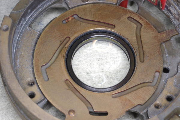
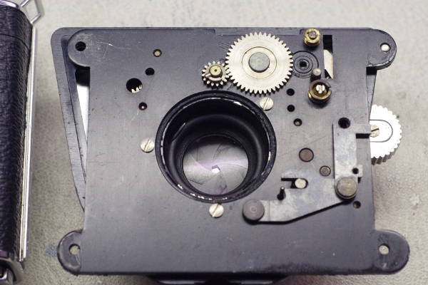
After removing the mounting plate earlier, this is what you’ll see on the standard.
Remove the gear marked by the left red circle, and discard it.
Pull off the gear, starwheel, and washer marked by the right red circle,
but keep them and note which way is “up” for each of these three parts.
|
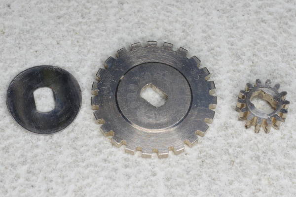 |
Here is a close-up of those three parts you’ll be keeping, in their correct orientation.
The washer on the left should be curved upward. The middle and right parts should be
nearly flat; when upside-down, you will see a hollow in them.
|
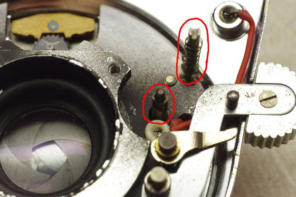 |
The pin-assembly in the upper-right red circle is part of the auto mechanism. Remove it.
Note the exposure-communication shaft to the left of the release lever (lower-left red circle).
This shaft communicates the ASA and shutter-speed settings (combined) to the meter
via the three parts you just removed and the cord.
Check that the button on the release lever (at the right edge of this photo)
is screwed on tight. This screw sometimes works loose.
|
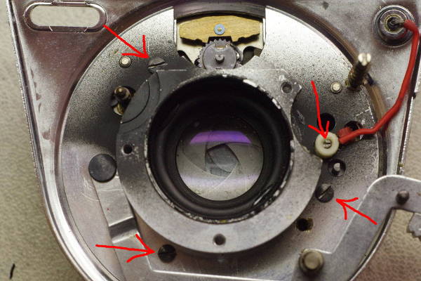 |
Unscrew the set-screw securing the red flash-sync wires, and separate those wires.
Unscrew the three black screws marked with arrows in this photo, and remove the standard from the shutter.
Removal might require substantial force if the standard has corroded onto the shutter.
First twist to break the bond, and then wiggle off the standard.
|
 |
Be sure to tighten these screws on the shutter-side of the standard.
There is also a third screw near the bottom of the standard to tighten.
|
 |
Here’s the back of the shutter. Note the release lever to the left of the red
flash-sync wire. The photographer releases this lever, which causes
the geared ring to rotate, speed-limited by the pallet on top, setting the proper
f-stop, and at the end of its rotation,
the shutter fires via the long lever that you removed inside the shutter.
Remove the geared ring surrounding the back of the shutter, and the brass pallet
above it.
|
 |
The geared ring is gone.
In my experience, there are two causes of most failures of these cameras:
- The geared ring has insufficient clearance (gap) between it and its supporting vinyl bushing,
so when underlying corrosion or perhaps hygroscopic swelling removes that gap,
the geared ring becomes stuck.
- The aperture is controlled by a rotor which has insufficient tolerance between
it and the shutter’s casing. Corrosion removes that gap, causing the rotor to stick.
So both failures are due to excessive German precision, and not the excessive complexity
of the auto mechanism.
Move the f-stop ring on the shutter between 2.8 and 22 several times.
The aperture should move accordingly, without sticking.
If it sticks, you will need to service the shutter; I provide some tips for this
near the end of this article.
After removing the pallet and perhaps servicing the shutter, you can reattach the
standard and mounting plate.
|
 |
The shutter and standard can be reattached as follows:
- Carefully guide the shutter’s red flash-wire back through the hole in the standard,
taking care not to crush it.
- Attach shutter and standard with three screws. Warning: If shutter and standard
mate stiffly (with high resistance), there is probably corrosion on one or both. Sand those mating surfaces.
A stiff fit will distort the shutter casing, which can cause the aperture to stick
(which happened to me), and will distort the optical path.
- Connect the two flash wires using the set-screw in the plastic part.
- Attach the washer/starwheel/gear in that order, and then the release lever.
I suggest that you fire the shutter to ensure that all is working as expected.
|
 |
As circled in red in this photo, the release lever must slightly overlap the starwheel.
If they are touching each other instead of overlapping, the mounting plate won’t
fit on.
|
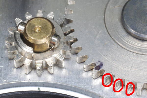 |
As you see here in the red circles, some teeth on these two gears can be worn.
Before re-attaching the mounting plate to the standard, rotate these gears so that the
end of the cocking-stroke, where mainspring force is highest, will be using teeth
with little or no wear. Don’t forget to check where the gear at the end of the
transfer shaft will mesh with this large gear.
You will need a loupe when examining teeth for wear.
The problem with worn teeth is they can make the advance stroke
feel toothy — sometimes very toothy in my experience.
|
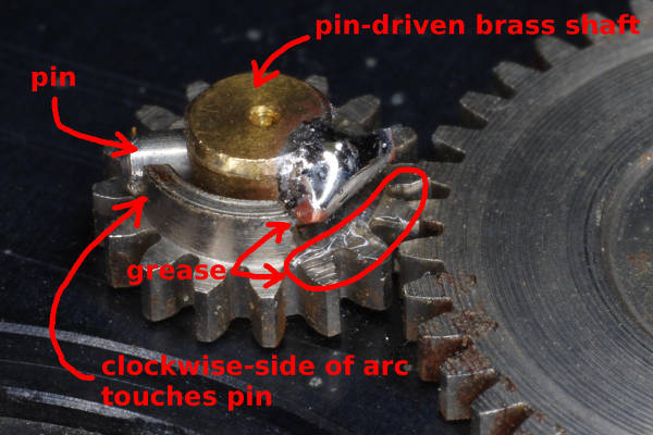 |
The other side of the shaft labeled “pin-driven brass shaft”
has two tabs that rotate a slot on the shutter, cocking it. During the production
of this camera, a design-change shifted that slot a little, making it slightly offset relative
to the center of this shaft. Thus, this shaft needs to wobble a little during the cocking stroke to accommodate
the offset of the shutter’s slot. However, because you removed the geared ring
a few steps ago, this shaft will not return to its original position on its own after cocking.
Firing the shutter would return it, but rotating the mass of the shaft would slow down the high speeds.
Therefore, you should solder a piece of wire to the brass shaft as shown, causing the shaft to
return when the steel gear returns.
You must orient the shaft and gear such that the clockwise side of the gear’s arc touches
the steel pin pressed into the shaft. This is the orientation during cocking.
To allow the shaft to wobble, it’s important that neither the wire nor solder touch
the gear. The small gap between the arc and wire is harmless.
Apply grease to the steel gear at the two locations shown
to prevent solder from adhering to those surfaces. I suggest sanding the brass surface
to remove oxidation before applying soldering flux to it.
|
 |
Here’s a top view of the soldered-on wire.
Cut the wire after soldering it, allowing you to hold it while soldering.
I used ordinary telephone wire with a diameter of 0.6 mm. Any solid copper wire
around this diameter should suffice.
If any solder is above the top of the brass shaft, file it down to the level
of the shaft so that it won’t touch the light baffle which is close to the shaft and gear.
The pin and wire together trap the arc between them, causing the shaft to follow the gear
in both directions, while allowing the shaft to wobble.
Force on these parts is very low during the return-portion
of the cocking-cycle, so the solder joint is more than strong enough.
In preparation for reinstalling the mounting plate on the body,
position the gear and shaft as shown in this photo. The arc should be centered either
directly above (as pictured) or directly below the shaft, with the pin touching the
clockwise side of the arc. This orientation causes the tabs behind the shaft to mate
with the shutter’s slot.
|
 |
Before placing the mounting plate (and shutter assembly) back on the body,
consider removing the release knob from the end of the release lever,
bending the lever up a little and covering it with heat-shrinkable tubing as shown.
When bending the lever, take care to not twist the portion of this part that is
under the standard.
The tubing will probably slide off the lever too easily.
To prevent this, pull it off the lever, put a little contact cement inside the tubing,
and press it back onto the lever. Also, I painted the exposed portion of the lever
black to match the tubing. An alternative I haven’t tried is to dip the end
of the lever in black Plasti Dip (liquid rubber). Plasti Dip is also useful for plugging holes
in curtains and light-leaks in bellows. You can also paint the lever, but the sharp edges
bothered my finger, so I prefer the rounded edges provided by tubing.
|
 |
You might find the camera to be more attractive without the conspicuous release knob protruding
to the side of the standard.
|
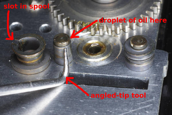 |
At this point, if you are going to use the meter, you should put a droplet of oil
at the spot shown to help the sleeve rotate as the cord runs over it.
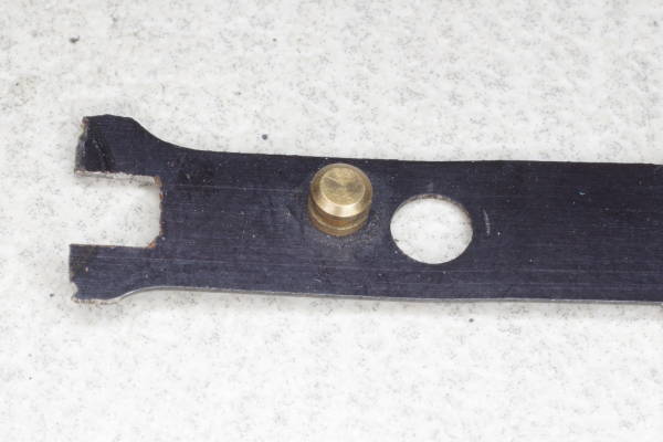
Note the angled-tip tool in this photo. This tool will greatly help in stringing the cord,
so much so that I regard it as an essential tool for this part of the job.
The sharp tip is only 4 mm long. If you lack this tool, you can probably make one by
bending a piece of coat-hangar wire and filing/grinding the end into a sharp point.
|
 |
I recommend replacing the original cord with braided fishing line.
I got fine results with lines having diameters of 0.31 and 0.32 mm, both 4-strand and 8-strand.
Line braided with 8 strands is preferable, but 4 strands will suffice.
In this article, I used a 208 mm length of the following fishing line:
Mounchain Extreme Braid 8 x 300M 40LB 0.32MM.
I have also used the following 4-strand 0.31 mm line with fine results:
Kastking KastPro Braided Fishing Line 40LB 150YDS.
I have not tried any other kinds of fishing line,
except that I first tried a 0.4 mm diameter line, which was slightly too large.
If diameter is not specified on the package or website,
select a fishing line with a strength of 90 to 110 kg (40 to 50 lbs).
If the line you want is out of stock, try selecting a different color.
On amazon.com, I find that some colors are usually in stock.
Also, 8-strand might only be available in certain colors.
You need 208 mm of cord, with knots on both ends to secure the cord to the slot in the spool.
You can tie knots 208 mm apart, but it’s difficult to position a knot accurately,
and you must do something to prevent the knot from slipping off the end of the cord.
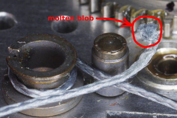
Instead of using knots,
you can make a replacement cord from braided fishing line by cutting your line to
220 mm (220=208+6+6), and then holding each end to a hot soldering iron to melt 6 mm of line into
a molten blob, reducing the length to the desired 208 mm between blobs. Important: hold the end of the line
to the iron, so you will be melting it end-first. The blob at the end will grow as you
continue melting. Also, the blob never touches the iron. The heat a fraction of a millimeter away
from the iron melts the line, causing it to withdraw from the iron as it’s melting,
so the two should never touch. The blobs are large enough that they will not pull out
of the slot in the spool.
|
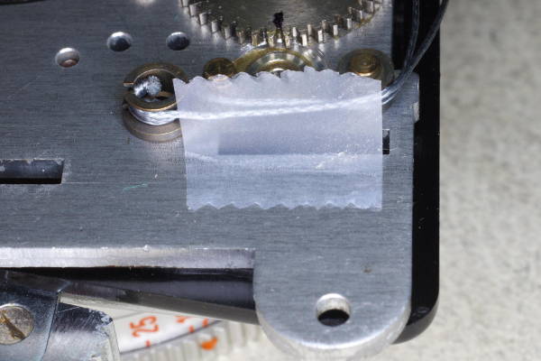 |
Attach the meter cord to the spool and pulleys on the mounting plate. Set the ASA to 10,
shutter-speed to 500, and double-check that the slot in the spool points down.
Then carefully thread both ends of the cord exactly as pictured in the disassembly-steps above.
After stringing the cord on the mounting plate, hold it in place with a piece of cellophane tape, as pictured here.
Keep the tape well away from the edges of the mounting plate so it will not get trapped between
the mounting plate and body. Also keep it away from where the cocking pinion will be located
(just behind the cords in this photo).
|
 |
Attach the shutter assembly to the body as follows:
- Rotate the large gear (mentioned above) fully clockwise. Doing so will cause the body to
not overcock the shutter.
- Pull the cord through the appropriate hole in the body.
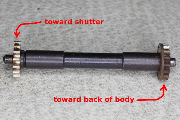
- Examine the teeth on the transfer shaft (shown in this photo), and identify a portion
having no wear.
- Place the transfer shaft into the body, after greasing both ends,
oriented so that the no-wear portion will be used at the end of the cocking-stroke (where mainspring
force is highest). It is important that the end with the open teeth face the shutter,
and that the end with the partly covered teeth face the back.
If you put this part in backwards, the camera will probably work fine,
but the rack will not be trapped properly, risking a failure.
- Place the correct screw (with the smaller head) into the upper-left hole of the mounting plate.
- Make sure the black light-blocking ring (if present) is still in the lens opening of the mounting plate.
- Hook the release linkages onto the pin on the body’s release lever, and install
the mounting plate onto the body. Assuming the body is lying flat on its back,
this step requires that you tilt the lower portion of the shutter assembly downward a little
to avoid disturbing the transfer shaft, shifting the assembly leftward to its proper position,
and then leveling it.
- Once everything mates together, attach the four screws securing the assembly to the body.
|
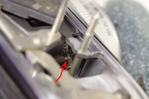 |
When placing the shutter assembly back onto the body, it’s nearly impossible to get
the cocking gear pin aligned with its hole in the mounting plate. But with the meter removed,
enough openings will be uncovered on the top of the body that you can
see where the transfer shaft is located (red arrow), and you can move it with
an angled-tip tool to position it correctly.
In this photo, you can see part of the large gear to the left of the gear at the red arrow.
You can rotate that large gear a little with your angled-tip tool to get those two gears to mesh.
|
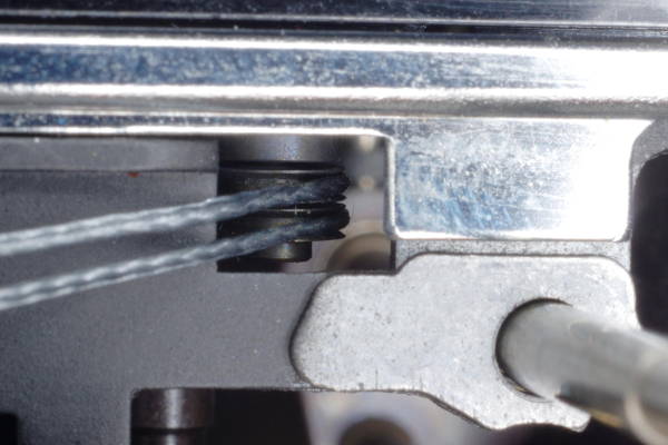 |
Looking down on the top of the camera,
check that the cords are passing over the pulleys on the mounting plate,
and that a cord is not off to one side or between the pulleys.
Also make certain that the two cords are not crossed.
You can look down the hole with a flashlight to check for crossing.
You can also check for crossing as follows: Rotating the shutterspeed ring
to a lower speed should move the cord closest to the lens upward; the cord
closest to the back of the camera should move downward.
Using cellophane tape, tape the cords to the top of the rangefinder or rewind shaft
to keep them taut enough to stay on these pulleys.
Reaching down with tweezers, remove the piece of cellophane tape from the mounting plate
that was holding the cords in place.
Try advancing a frame, which should cock the shutter. If the large gear
above was rotated fully clockwise, you should not overcock the shutter. But it might
be undercocked.
|
 |
Remove rings and plates from the front of the shutter until its mechanism is exposed.
Be careful to maintain the proper mesh of the toothed plate and the gear it drives.
Cock the shutter using the advance lever. If you see that it does not cock far enough,
peform the following steps:
- Remove the plate that holds down the rack. Doing so requires removing two screws.
Remember: Never cock the shutter without first reinstalling the plate screw.
- Move the cocking tab circled in this photo a little to the right, which rotates that part
anticlockwise. It should not be far from where it is in this photo.
- Re-attach the rack plate, and try again.
Once those gears are synchronized correctly, you will be able to cock the shutter
using the advance lever, and fire it by pushing the final fire-lever, which is identified below.
|
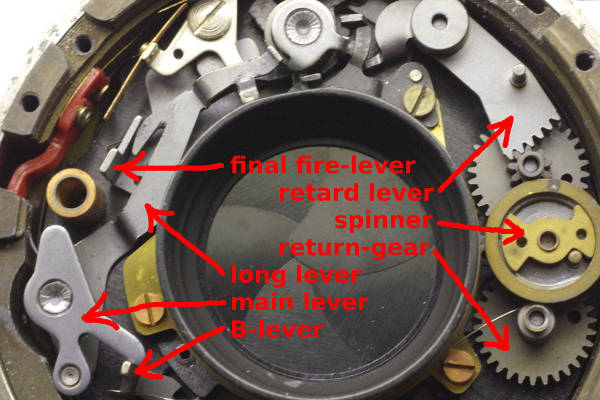 |
Here’s the inside of the shutter, with parts labeled that you need to know about.
You removed the long lever several steps ago. In case you were wondering,
a rotating tab presses the top-end of the long lever, which in turn presses the
final fire-lever, firing the shutter.
You need to fire it from the main lever instead,
which is why you removed the long lever.
The final fire-lever directly fires the shutter. In the steps below, you will attach
an arm to the main lever which will move the final fire-lever, firing the shutter.
In this photo, you can see the retard mechanism on the right side of the shutter,
with three of its parts labeled in red.
In the middle of this mechanism, at the 3:00 position of the shutter, there is a
brass spinner. I recommend that you clean and lube the bearing and axle of the spinner
with moly powder and/or watch oil.
To put the spinner back, you must correctly position the return gear
and its spring. Assemble any parts you removed from the retard mechanism,
but leave the spinner out. Cock the shutter.
Rotate the retard lever as far clockwise as possible.
Rotate the return gear until the tail of its spring touches the shutter’s
throat. Rotate it 1/4 turn more, and holding it in this position,
install the spinner. To check the mechanism, rotate the retard lever as far
anticlockwise as possible, and slowly release it. Even with such slow release, the retard lever should
return to the maximum clockwise position, driven by the spring around the return gear.
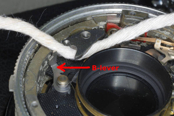
Fire the shutter while holding the B-lever (8:00 position) outward, and the speed should be 1/30th.
That 1/4 turn is what I’ve seen on multiple cameras, so I believe that’s what the factory used.
However, you can reduce shutter speeds by rotating the return gear by more than the 1/4 turn recommended
above, and likewise you can increase speeds by rotating it less. If you can measure speeds,
I suggest rotating the return gear such that 1/30th has the correct time; the higher speeds
should fall into place. But I’ll caution you against going much over 1/2 turn because I tried
3/4 turn on two cameras, and their mainspring was unable to (slowly) push the retard lever through its complete
movement, which would jam the shutter.
|
 |
The following steps solder the brass pallet to the underside of the main lever.
But first, you must clean that underside as follows:
- Disconnect the return spring on the B-lever.
- Swing the B-lever out of the way (as pictured).
- Place a thin strip of sandpaper under the main lever (instead of the string that is pictured).
- Slide it back and forth to remove the plating on this lever, exposing the brass underneath.
Solder adheres much better to brass than this plating, so diligently sand off the plating.
- Blow out the powder from sanding with compressed air.
- Place a string under the main lever as pictured, wet the string with a few drops of naphtha
or acetone, and slide it back and forth.
- Re-attach the B-spring to the B-lever.
|
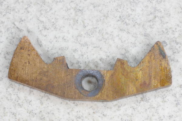 |
Here is the brass pallet you removed earlier.
|
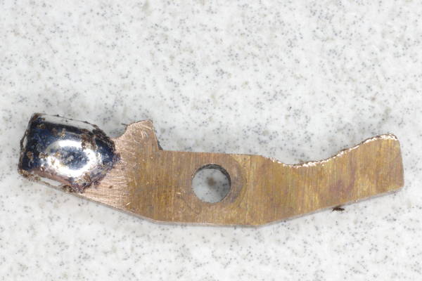 |
Cut or grind the teeth on the pallet until it looks like this. I used a Dremel for this chore.
Sand the end as shown, and tin it with solder. “Tinning” means applying solder ahead of time.
Space is tight in the shutter, and if the thickness of this blob prevents this part from fitting
under the main lever, you will need to file down the blob a little to make it thinner.
|
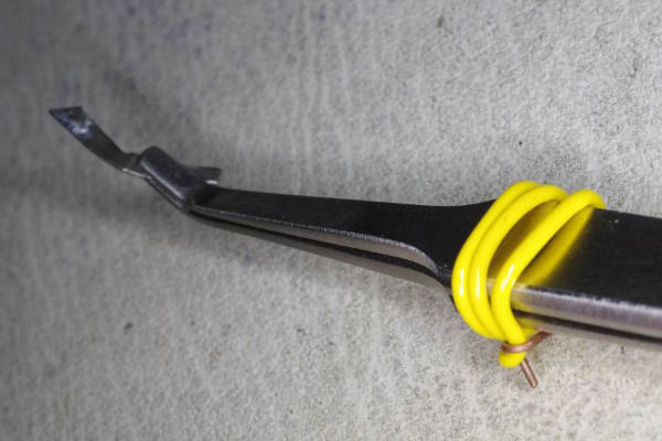 |
While soldering it, you will need to hold the pallet with angled-tip tweezers. Tying the ends together with
electrical wire as shown makes the delicate task of soldering easier because you won’t need
to constantly squeeze the tweezers.
I found that this trick eliminates all finger-shake while trying to solder.
In this photo, the tweezers is holding the long lever (cut to appropriate size) instead of the pallet.
Both are suitable, but as I mentioned earlier, I prefer brass because solder adheres well to it.
|
 |
Do the following in preparation for soldering:
- Temporarily attach the top-cover to the camera. The meter need not be re-installed.
- Cover the shutter’s throat so that boiling soldering paste won’t splatter onto the blades.
I covered it with cellophane tape.
- Disconnect the spring on the final fire-lever.
- Cock the shutter using the film-advance lever.
- Attach a cable-release to the top of the camera, and press it down as far as it will go.
Be sure it hit the end of the camera’s travel.
If your cable-release reaches the end of its own travel before it’s stopped by the
camera, add a 5mm slug as described here a few steps below.
- Lock the cable-release at this position.
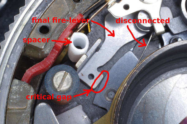
- Manually fire the shutter by pressing the final fire-lever.
It will remain open (on B) because the main lever is in the fired position and thus is not pressing the B-lever.
- Place a spacer of some kind (pictured) so that the “critical gap” (as shown)
is about 0.3 mm. If this gap is too small, the shutter might not always fire from a cable-release.
If too large, it might not remain open on B, making B behave like 1/30. The spacer I used is part of
the plastic stem of a cotton bud/swab/Q-tip. A bamboo skewer or thick wire or sliver of wood would work.
- Apply soldering paste to the appropriate portion of the underside of the main fire-lever.
In these cameras, the mechanism for the cable-release has slightly less travel than the release lever.
Thus, if the critical gap is too small, you could probably fire the camera from the
lever but not from a cable-release.
|
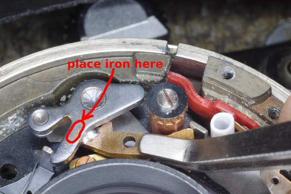 |
The following steps solder the arm onto the main fire-lever:
- Smear a very thin layer of grease on top of the main fire-lever
in the area marked “place iron here” in this photo.
The grease prevents solder from sticking to the top of the main fire-lever.
- Put a moderate sized blob of solder on your iron.
- Use the tweezers to position the long lever as shown.
While holding the long lever, you must be pressing upward on its
left end (against the underside of the main lever) and pressing its right end
against the final fire-lever to maintain the critical gap.
- Place your iron on top of the main fire-lever at the position shown.
- The solder on the arm (being held by your tweezers) will melt in a 10-30 seconds.
Continue applying heat a little longer to ensure adhesion.
This kind of angled-tip tweezers is uncommon in the marketplace,
but they’re invaluable for a chore like this.
|
 |
Here is the result. At this point, you need to:
- Clean off the grease on top of the main fire-lever and the excess soldering paste.
- Remove the spacer from the shutter.
- Re-attach the spring to the final fire-lever.
Watch out for any tiny remnants of solder lying about.
Such bits are referred to as “FOD” in industry, which
stands for “foreign object debris”. It’s deadly in electronics.
It can only cause trouble in a shutter, so eliminate all FOD resulting from soldering.
After this modification, the main lever will fire the shutter, as well as close the blades on B
(its original purpose).
This modification works well. Advance and fire the shutter a few times as a photographer would,
checking that both B-speed and cable-release operate properly.
This is the kind of work you can be proud of.
By the way, this is how the shutter in the Retina IIF is constructed: Its main fire-lever
has an arm reaching over to the final fire-lever, whose shape is nearly identical to the arm we just added.
To attach the arm, I used Superglue in the first cameras I modified instead of solder.
The arm was pressed up against the main lever by a little piece of foam rubber under it (instead of tweezers).
Superglue is strong enough, but solder is stronger, giving us more margin against failure, so I switched to solder.
If your hands are so shaky that you cannot hold tweezers steadily, consider using Superglue instead.
Epoxy should be stronger than Superglue, but I’ve never tried it.
|
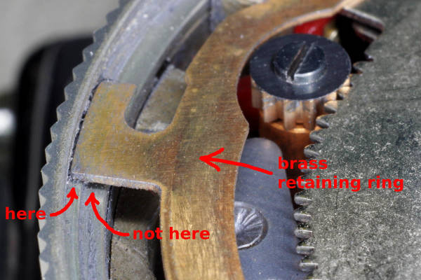 |
You may now reassemble the shutter and lens assembly. Be careful to maintain the original
mesh of these two gears.
When installing the pictured brass retainer ring, note that the
tabs on this ring should rest on the outermost (raised) surface as shown (marked “here”
in the photo).
If a tab is on the inner (lower) surface marked “not here”, the brass ring has
probably not snapped into its mating slot encircling the inner wall of the shutter casing.
|
 |
Re-install the meter.
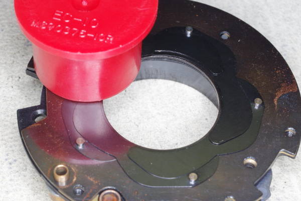
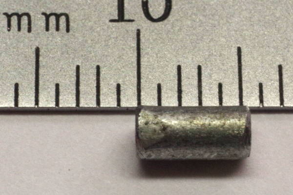
Here’s a problem with the Retina Automatic III camera: The cable release at the top
requires that the actuating pin at the end of the cable extend a long distance, and some
cable releases might not reach far enough. You can reduce the required distance by placing
a slug (spacer) in the brass tube below the release at the top. This tube has a diameter of 3 mm,
so you need something a little smaller. Around here, hardware stores sell “hanging wire”
intended for hanging false cielings, and this steel wire is 2.6 mm thick (10 gauge).
That’s good enough. A suitable nail will also work.
Cut a piece that is 5.5 to 6 mm long as shown.
Round the edges of your cuts (as seen in this photo) so that sharp steel edges won’t
cut into the brass tube.
|
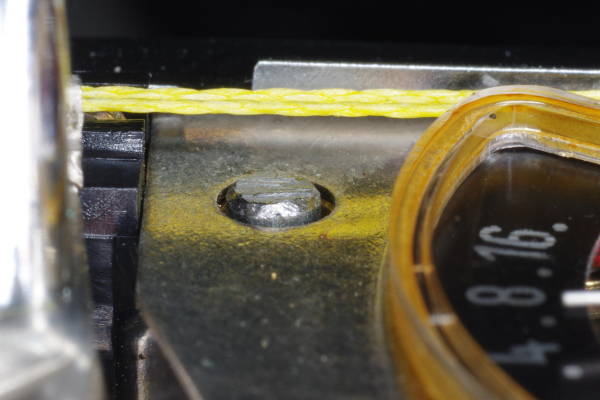 |
In this photo, I have placed the slug into the cable-release tube, which is part of the meter assembly.
It should protrude no more than 1 mm above the metal surface of the meter.
If you are not going to use the meter, then put the top-cover back on, check that everything works,
and you’re done.
But if you need the meter, the following steps show how to restring the meter cord.
|
 |
It is not possible to restring the cord over the studs and through the ends
of the spring, while the spring is pulling on the cords. After some
experimentation, I settled on the following steps for restringing the meter.
For a second-version camera (with the large cell):
Being careful that a cord doesn’t hop off a pulley shown above, change
the ASA to 100 and shutter-speed to 125. In the following steps, try to keep
the opening of the large pulley facing straight down, as this position will be close
to its correct calibration.
I don’t know the calibration position for a first-version camera (small cell).
Use cellophane tape to hold the cords in place at the upper left corner of
the meter. This photo shows part of that piece of tape.
The cords run over the meter’s vertical pulleys (not pictured).
As shown, install the left small pulley, but not the right pulley
because it will get in the way when stringing the left pulley.
On the large pulley, arrange the cord as shown.
|
 |
Hook the cord to one side of the spring, push it into the groove, and hook its other side.
Cut a separate length of scrap cord (yellow in these photos) around 15 cm (6 inches)
long. Tie it into a loop, passing through the loop of meter cord as shown.
|
 |
Push the meter cord passing over the large screw into the bottom portion of the groove.
|
 |
Using your angled-tip tool (pictured earlier), string the left cord over the upper left pulley.
|
 |
Put on the upper right pulley, and string the right cord over it. This will
stretch the spring and tension the cord. Now you can remove the tape mentioned above.
|
 |
Calibrate the meter now, because at this point, moving the cord back and forth through the large pulley
is easy. As part of calibration, center the spring in preparation for the next step.
|
 |
Install the cord-lock screw as follows:
- Insert one of your fingers into the loop of scrap cord, and pull it, creating
a triangular opening as shown. Continue pulling on it until you cut it below.
- Place the cord-lock washer over the meter cord, with its top edge under the lip of the large screw
in the middle of the large pulley.
- Put the cord-lock screw in its hole, but only turn it 1-2 turns; do not tighten the screw.
- Cut the scrap cord as close to the meter cord as possible, and pull it out.
- Tighten the cord-lock screw.
|
 |
The restringing and calibration are done.
|
 |
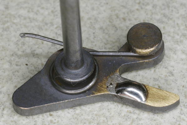
When reassembling the camera, you might have needed to remove the bottom plate, and if so, you need
to reassemble the rotating spring-returned release-cover surrounding the tripod-mount. That tiny
spring can easily jump away, but here’s a trick to reassembling it without losing this spring:
Assemble the pieces on your work-mat as shown, with only one screw inserted as shown. Insert the
spring last. Then pick up the assembly by only touching the round cover-piece,
thus ensuring that the two large pieces stay together,
and push the assembly onto the tripod mount. Doing so pushes the screw out some, but everything
will stay together. When pushing on the assembly, keep the assembly in the orientation pictured here,
with the screw pointing up, causing you to push the assembly up onto the bottom of the camera.
Then tighten the screw in it, and then put in the other screw.
|
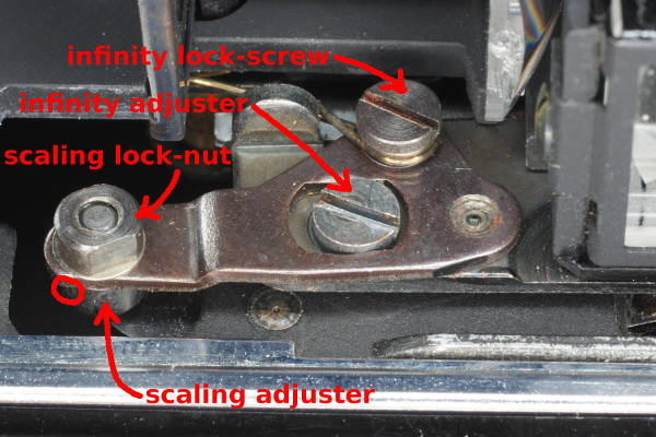
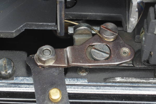
It appears to me that the scaling adjustment in the rangefinder in this camera was calibrated
to the focus scale and not to the lens. This adjustment determines accuracy of focus
at close distances, and changing this adjustment can affect the infinity adjustment. I suggest focusing at
a close distance using the camera’s rangefinder, and comparing that focus-scale number with what
you obtain by focusing on a groundglass placed on the film-window. But you should check focus well
off-center with your groundglass. The reason is that these lenses can have substantial curvature
of field, with a hump in the center. Most lenses of various brands have a center-hump, so focus
should always be checked off-center.
If RF and best focus on groundglass are substantially different,
then the rangefinder does not match the lens at close distances.
You will need to remove the top and change the scaling adjustment.
WARNING: Before changing the scaling as described below, first verify that the infinity focus
of the lens is correct. Sometimes a dufus will change the focus adjustment of the lens
using the three set-screws that secure the focus-ring to the lens. If you are certain that: