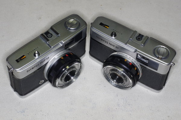
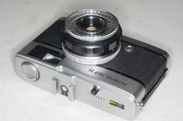
In this article, “left” and “right” assume that you have the camera pointing toward you.
So the rewind lever is on the right side, and the frame-counter (on top) is on the left side.
If you only wish to clean the aperture or shutter blades, and are NOT going to make the
manual-speed modification, then you can skip the beginning steps below telling you to
remove the top- and bottom-covers of the camera.
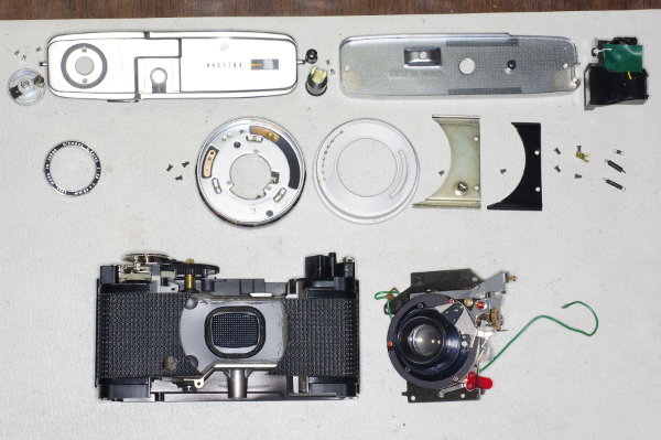 |
During disassembly, place the parts left to right on your work-surface,
in rows starting at the top of the work-surface.
During reassembly, go through the parts in reverse order, thus ensuring that the assembly-order
will be correct and that no parts will be left over.
In this photo, I have two rows of parts. Your rows of parts should look almost identical.
Now, let’s get started with the modification. |
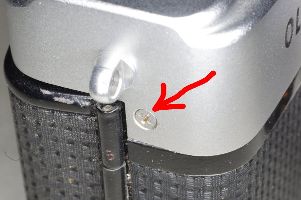 |
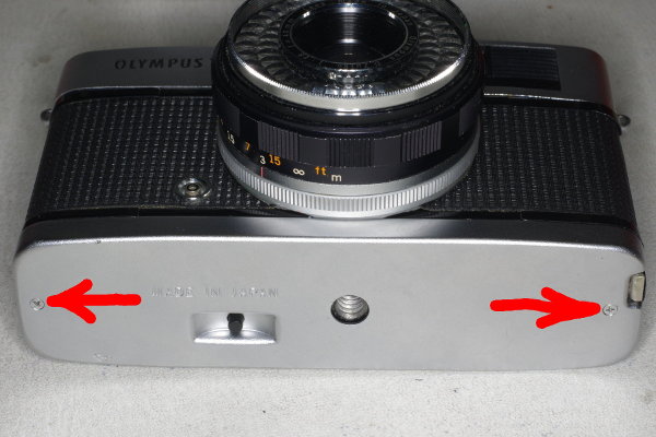
First, remove the top plate. Unscrew this screw on the right side by the strap-lug.
|
 |
Then block the rewind-fork with something flat. I use the handle-end of my tweezers for this.
Then you can turn the rewind-crank counterclockwise to unscrew it.
|
 |
Removing the rewind-crank reveals two more screws securing the top cover. Remove them.
Notice that there is no dust in this cavity. That’s because I cleaned it out with
a toothbrush. I suggest using a toothbrush to clean parts as they are removed or reassembled.
|
 |
Pull off the top cover with the camera laying horizontally on its back so that the shutter-button
will not fall out of the cover. After removing the cover, remove the shutter-button.
Also, pull back or remove the electrical tape that joins the green and black wires together
(the black wire goes to the hot shoe).
Unsolder the connection, separating the wires.
|
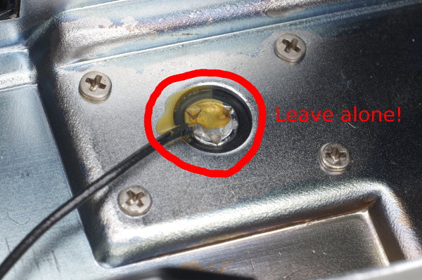 |
Here’s the black flash-sync wire at the hot shoe. Do NOT unsolder this. Doing so will melt the
surrounding plastic and cause the metal connector to fall out. Don’t ask how I know this.
|
 |
Pull out the rewind-shaft assembly. It’s not attached.
The plastic sleeve being held with my fingers in this photo is metal in earlier cameras.
|
 |
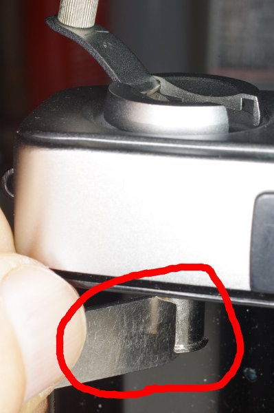
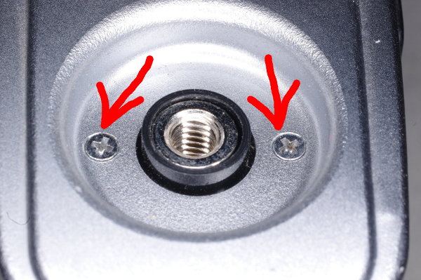
Remove the bottom plate by unscrewing its two crosspoint screws.
|
 |
The rewind-release button is held on by friction. Pull it out so you won’t lose it.
|
 |
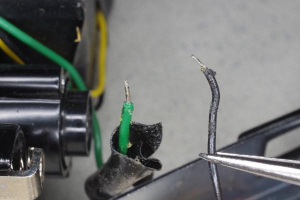
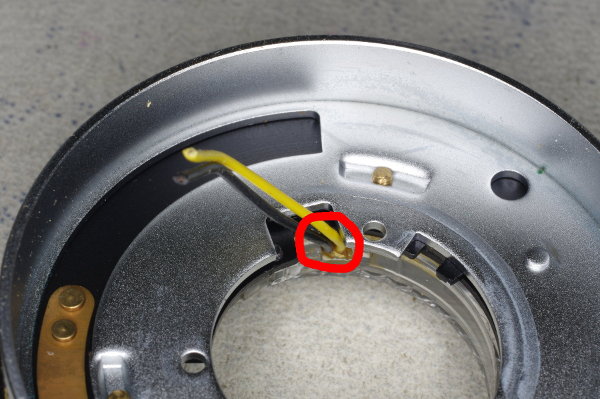
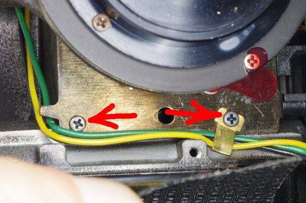
Cut the black and yellow wires at the indicated position.
These go to the selenium cell to control the meter,
which you won’t need any more.
The green wire is your flash-sync; leave it alone.
|
 |
We will now prepare to remove the front element of the lens. Set the focus to infinity.
|
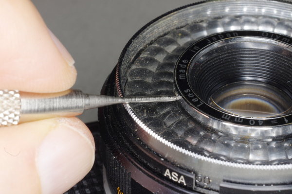 |
Use a jeweller’s screwdriver to loosen the three set-screws on the inner focus-ring by two turns.
Two turns is enough; you don’t need to remove these screws.
|
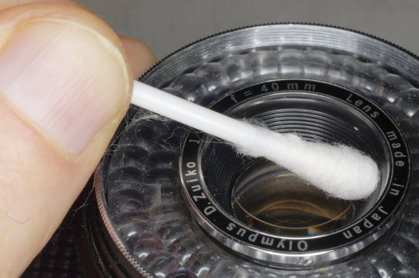 |
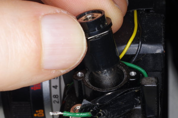
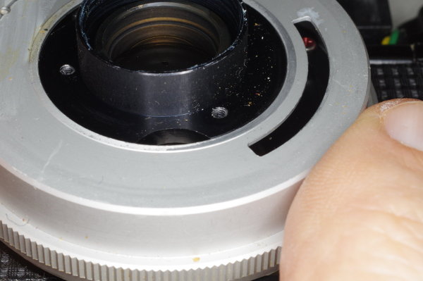
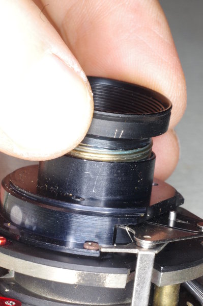
Here’s a tricky step: You need to remove that focus-ring without rotating the lens.
And the lens rotates effortlessly, so you must be careful.
One way to prevent rotation is to block the lens by pressing firmly on it
sideways with a cotton swab as shown,
and lift the ring, with the swab passing through the ring.
|
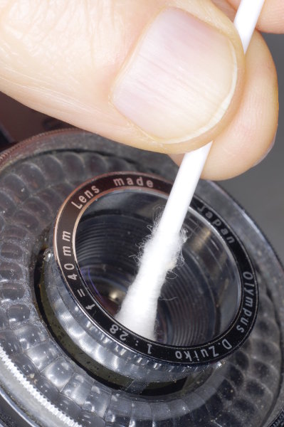 |
I am blocking the lens here with the swab, and the inner focus-ring is partly out.
|
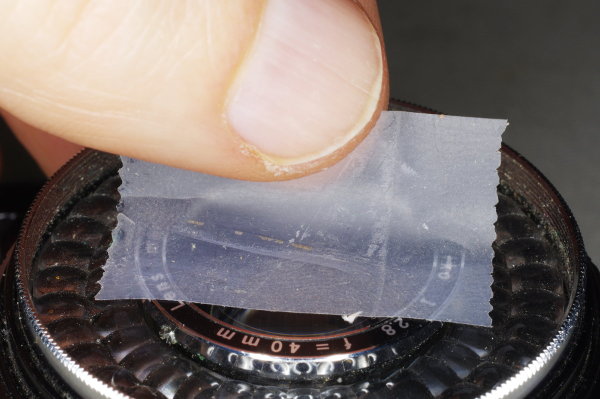 |
An alternative is to carefully lift the ring with a piece of cellphane tape.
|
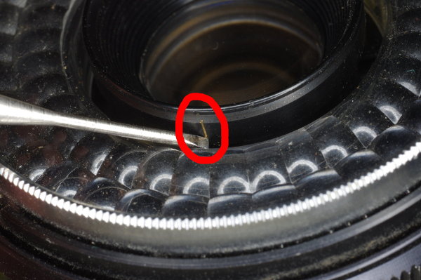 |
Mark the position of the lens by making a scratch as shown with the tip of a screwdriver
aligned with a screw underneath.
There might already be a scratch on this part from the factory.
If so, check to see what it’s aligned with.
|
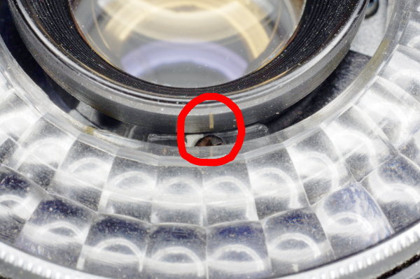 |
From this viewpoint, we can see the screwhead that my scratch is aligned with.
|
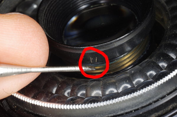 |
Rotate the lens until it just comes free. Then put two scratches on it by the same
screwhead. The threads for the lens can enter at two positions; i.e., these threads
have two starts or entries. On reassembly, you need to begin threading at the
correct starting position.
|
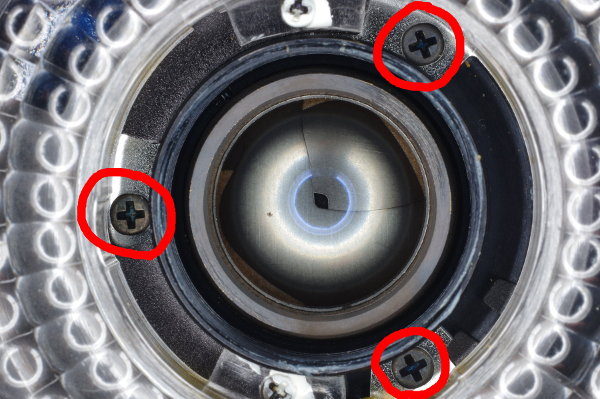 |
Remove the three screws securing the front ring-assembly.
Note that these screws are lower than the other two screws in this photo.
Pull off this ring-assembly, taking care to hold the aperture-ring down so it won’t
lift off as well.
|
 |
A tiny ball will be in the back of this assembly as shown, or it might be on the aperture-ring
on the camera. Remove this ball. Actually, I prefer to leave it on the ring-assembly as shown,
but secured with a small dab of grease.
|
 |
If you plan to make the manual-speed modification,
cut these wires as close to the Selenium cell as possible to keep them out of the way
when reassembling.
|
 |
The aperture-ring can be lifted off.
|
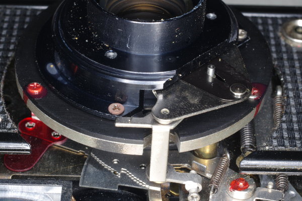 |
This is what you’ll see after lifting off the aperture-ring. The mechanism that automatically
selects aperture and speed are at the bottom of this picture.
You will modify this mechanism.
If you want to clean the blades because they are sticking due to oil on them,
you can do so now without disassembling the camera any further.
CLICK HERE for instructions on cleaning blades.
|
 |
Pull up the leatherette on both sides of the shutter assembly. This is easy on later cameras
because the leatherette is secured with double-stick tape.
Earlier cameras used glue, and their leatherette is difficult to peel.
Start in a corner with a jeweller’s screwdriver as shown, and be patient.
|
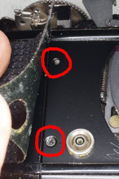 |
Peeling enough leatherette reveals the side-plates, one on each side of the shutter-assembly,
which are secured by one or two screws (one screw in later cameras).
Unscrew it/them on both sides, and remove the plates.
|
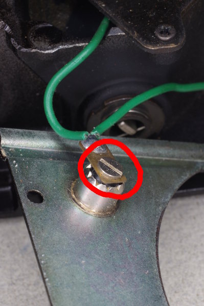 |
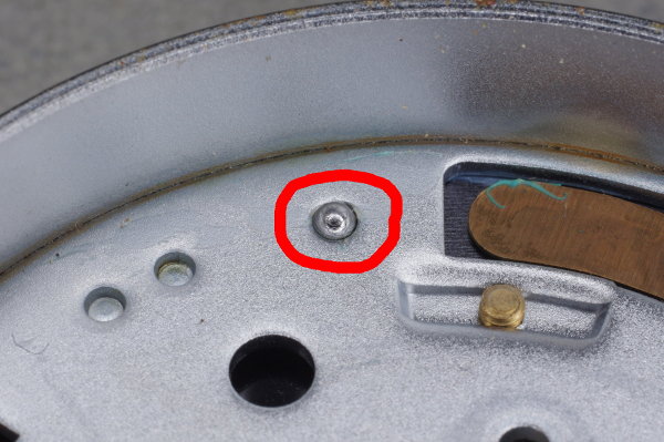
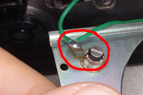
The green flash-sync wire is soldered to a lug that is secured by a screw.
Loosen but do not remove this screw.
When reassembling, be sure this lug is oriented as shown (pointing up).
|
 |
The lug slides out once the screw is loose.
|
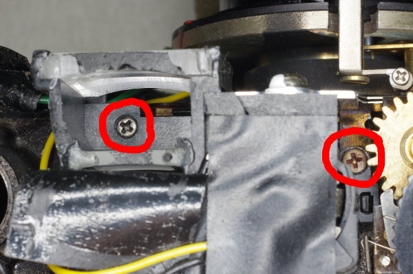 |
We are looking down at the top of the camera, at the viewfinder-meter assembly,
with some tape or covering over the viewfinder pulled back. You can see that this
assembly is secured by two screws. Unscrew them completely, but leave them in
the assembly, and pull out the assembly.
But first cut the black and yellow wires.
|
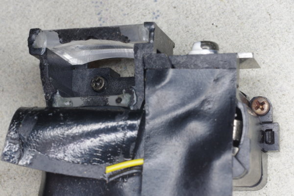 |
Here, you see the viewfinder-meter assembly sitting on my work-mat, with the screws still in it.
Notice the cut wires.
|
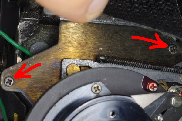 |
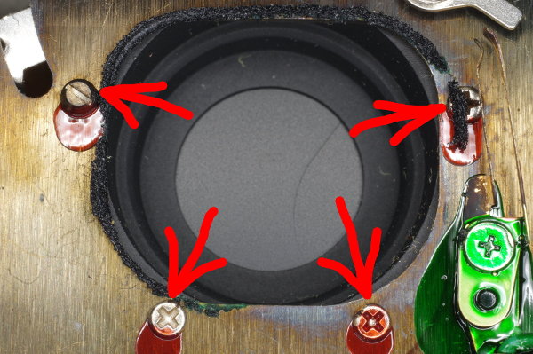
The large shutter-plate is secured by four screws, and here are two of them,
which you must remove.
|
 |
Here are the other two screws on the right side of the shutter-plate.
Remove them, and pull the shutter-assembly up and out of the body.
|
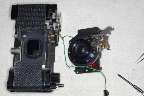 |
Here is the body and the separated shutter-assembly. Note that there is a thin ring of
light-baffling foam around the opening on the back of the shutter, and around the lens-opening
(cowl) on the body. Try not to disturb this foam, unless you plan to replace it.
|
 |
To prevent dust from sticking onto the grease in the focus-threads while servicing the shutter,
I like to screw the front element of the lens back on.
|
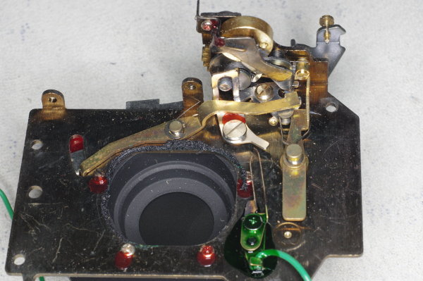 |
Here’s the back of the shutter-assembly. There are two variations in this design,
and the lever-arm in the left half of this picture differs based on which design your camera used.
I cover both variations in this article,
and I call them “variant 1” (the earlier design with the metal shutter-button)
and “variant 2” (the later design with the black plastic shutter-button).
|
 |
One or more of these four screws often loosen over the years.
If the shutter-assembly is loose, these screws are probably the culprit.
Tighten them if necessary, and lock them with Locktite or glue or paint.
|
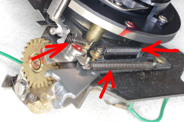 |
Remove all three of these springs with your tweezers. You will be reusing the front and
rear springs, but not the middle one. A spring can fly away if it slips off your tweezers,
so press against one end of a spring with a finger while releasing the other end.
|
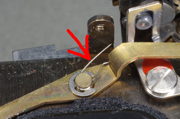 |
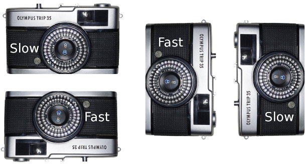
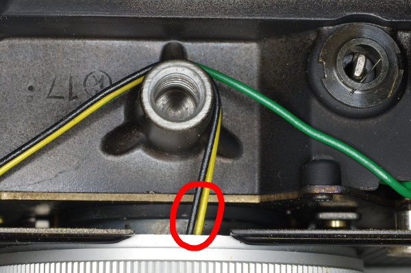
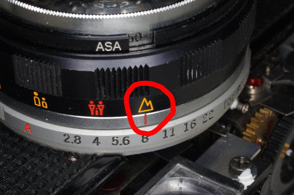
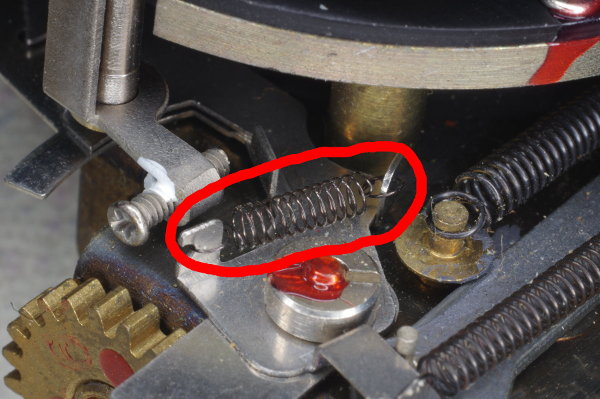
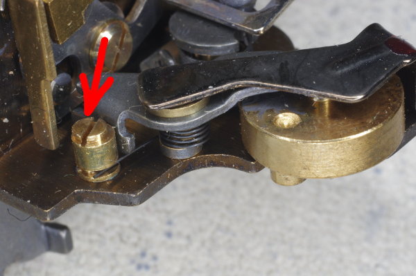
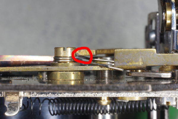
I call this long brass horizontal arm the “speed-lever”
because it selects the shutter-speed (1/40 or 1/200).
Remove the hairspring at its center (refer to the red arrow), causing the lever to move freely.
|
 |
This is variant 1 of the auto mechanism.
|
 |
And this is variant 2. As you can see, there are minor differences.
In either case, you will break off the left portion of the long lever, as shown in the next
two photos. I put a black mark on the lever at the break-point. The location of this
break does not need to be accurate.
|
 |
You can cut off the left portion with a small wire-cutter.
Alternatively, as shown in this photo, you can use
a needle-nose pliars to hold the right portion of the lever immobile, and
repeatedly bend the left portion of the lever back and forth with your fingers
until it breaks off (due to metal-fatigue) near the black mark.
|
 |
This is the result.
|
 |
The hairspring in this photo pushes the two-blade aperture toward the closed position.
For manual aperture control, we need it to be pushed toward its open position, so the
hairspring in this photo must be removed. The next two photos show how.
|
 |
The left end of the hairspring in the prior photo can be unhooked and moved into the open
as you see in this photo. Then you can cut off the hook portion as shown.
|
 |
Grab the other end of the hairspring with needle-nose pliars as shown, and pull it out.
Don’t pull hard, or you might damage the surrounding aperture mechanism.
|
 |
This is what the hairspring will look like after you pull it out.
|
 |
The shutter-plate is made out of brass which bends easily.
In addition, much of the top edge of the plate has no backing from the body-casting,
making the plate prone to bending in a frontal blow to the camera.
Variant 1 plates are especially weak because it has a long curved slot that reaches to the top,
removing strength from the top of the plate.
You can check flatness by placing a straightedge along the unobstructed portions of
the plate, both front and back.
If you don’t straighten a bend, then your lens will be tilted slightly,
defocusing the top and bottom areas of the negative.
|
 |
If you detect warpage, you’ll need to remove everything that can be conveniently removed
from the plate.
Here’s the front of a variant 2 plate with the shutter-assembly removed (I unscrewed those four
screws I warned you about above). As you can see, the bend is severe.
This camera suffered a hard jolt to its nose.
|
 |
I suggest placing the unobstructed portions of the plate on a small piece of flat wood
and hitting it with a dowel until your straightedge-checks show that it’s sufficiently flat.
In fact, the brass plate is so weak that you do much of the straightening with your fingers
and a pliars: Hold one part with the pliars, and carefully bend the rest by hand.
This photo shows the above plate after 10 minutes of careful bending and hitting, and rechecking flatness.
It’s close enough to flat.
|
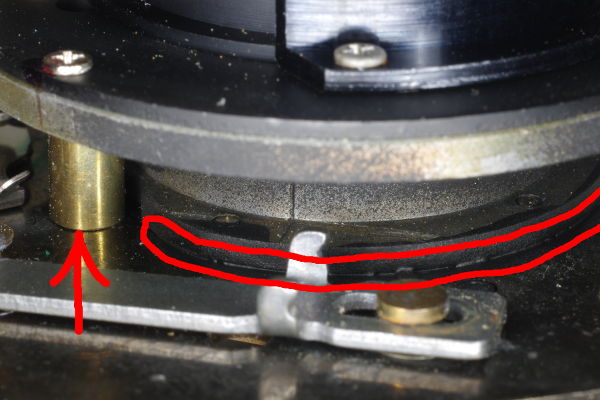 |
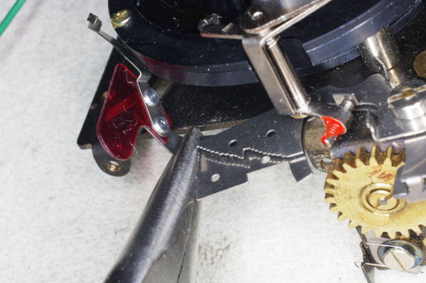
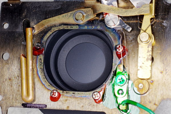
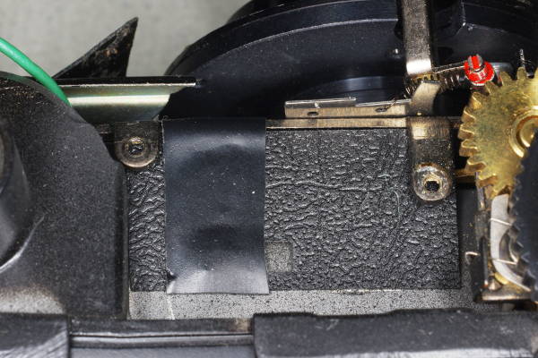
You won’t get the plate perfectly flat, and to avoid having light sneak past
the shutter-tube after you attach it with those four screws, I suggest applying
black paint to the junction of the tube and plate as shown by the long curved red lines
in this photo. The paint will fill the gaps.
But don’t paint near the brass rod on the left (red arrow), because
it needs to rotate freely, and paint will jam it. Instead, apply black paint to
the inside of the tube in the area near the rod.
|
 |
Remember the smallest of the three springs you removed? Here’s another photo of it.
You’ll need it in the next step.
|
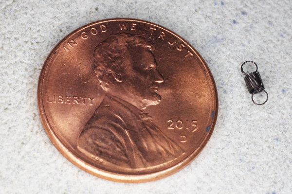 |
Because I shot these photos using a macro lens with a 25mm extension tube,
that spring looks large in the prior photo. But this photo gives you an idea of how
small it actually is. It’s not much bigger than an ant.
|
 |
Using tweezers, hook the ends of that tiny spring into the hole on the left
and the screw on the right.
As you saw, this spring is tiny, and it’s easy for it to slip while attempting to
install it, causing it to fly away, never to be seen again. Keep a finger
on one end of the spring while manipulating the other end with your tweezers.
I suggest installing the left end first (onto the lever), as that is more difficult than
hooking it over the screwhead, and this chore is easier when the spring is not under tension.
|
 |
The spring has been installed, and is pulling the aperture into its wide-open position.
Pushing down on the screwhead (at the right end of the spring) should close the aperture.
This is a variant 2 mechanism.
|
 |
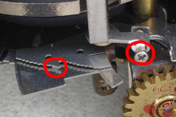
This is a variant 1 mechanism.
It’s similar, but there’s a fourth hole we used that’s at a better location.
I don’t know what these holes are for,
but I use them as a convenient place to attach this little hold-open spring.
|
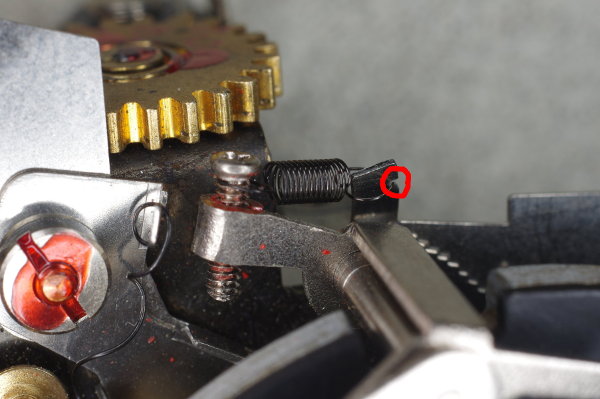 |
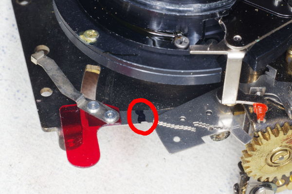
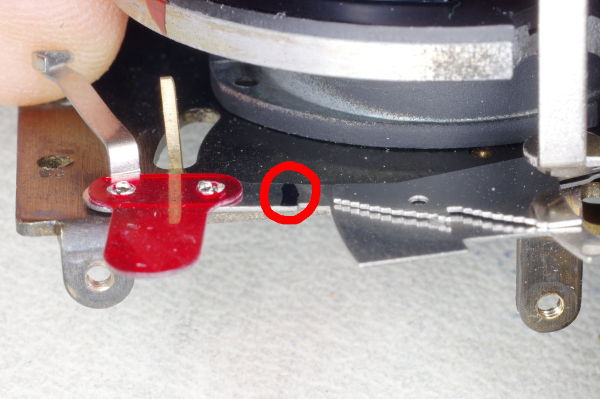
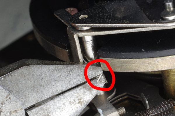
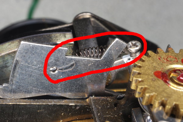
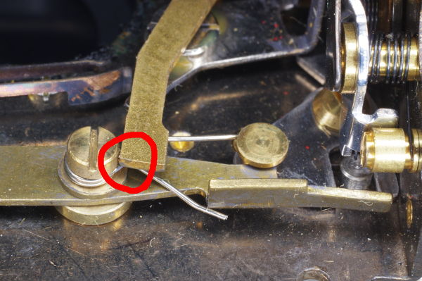
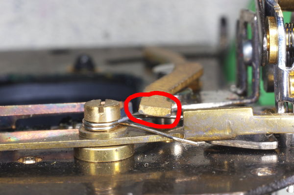
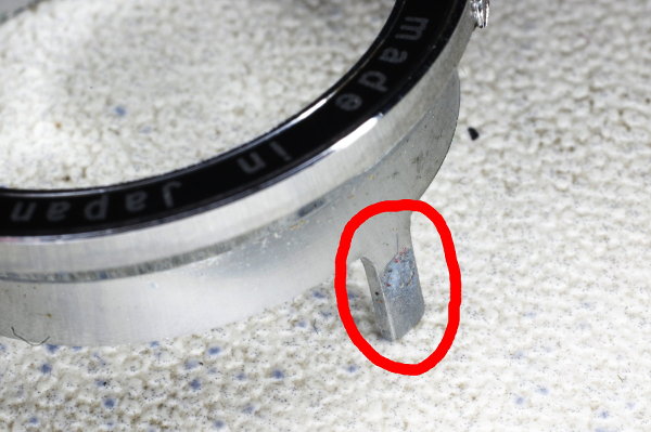
There is a tall piece of metal near where you want the spring. You can file a notch
in it (circled in red), and attach the spring to that. But to prevent the levers from
moving and causing this spring to slip off and fly away,
I suggest attaching this spring after moving some other springs in the next steps.
|
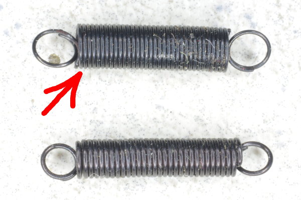 |
In some cameras, the two longer springs that you removed earlier
are about the same length when relaxed.
You need to use the one made out of thinner wire (top one in this photo).
|
 |
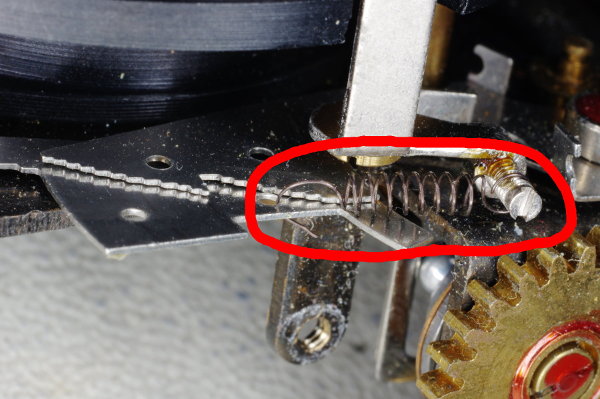
Attach the spring as shown. This spring serves two purposes: (1) it holds the
auto levers down, keeping them out of the way, and (2) it provides upward force
on the shutter-button.
|
 |
I prefer that a shutter-button have a light touch, so I’ve stretched the spring some
here to weaken it, reducing shutter-button force.
|
 |
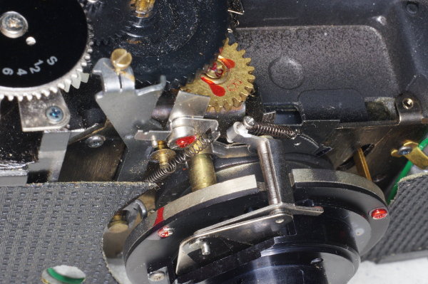
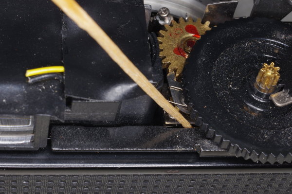
The flywheel on the right side of this picture provides a retard to yield
the 1/40 (slow) speed. The adjuster on the left is eccentric, allowing you
to adjust the slow speed. After all these years, 1/40 is sometimes too slow, and you can adjust it
by turning this adjuster. You can wind the shutter by hand-turning the gear on top by one revolution,
and then fire. Adjust until the speed seems about right.
|
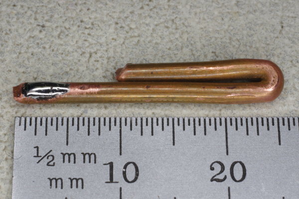 |
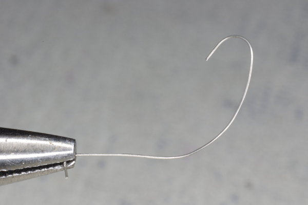
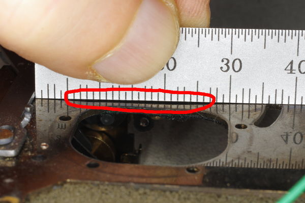
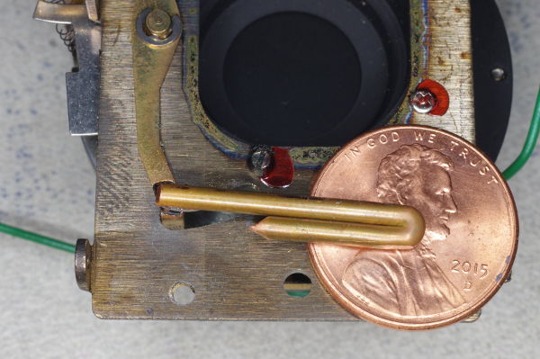
The manual-speed modification requires that a weight be attached to the end
of the long speed-lever. Cut and bend a piece of 10- or 12-gauge house wire
as shown. The short portion is about 15mm, and the long portion will be 24-25mm.
You can make it 1mm or 1.5mm longer, as I did in this example.
Why 24-25mm? Because, at the low-speed setting,
the bottom of this wire will touch the floor of the cast metal body
which serves as a stop for the wire.
A distance of 24-25mm (measured from the top edge of the speed-lever)
will result in the ideal lever-position for the low speed.
|
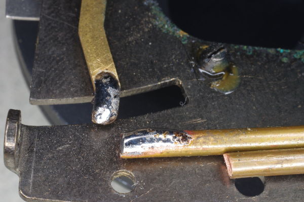 |
Tin the ends of both the speed-lever and the wire.
I suggest covering the large opening to the shutter blades
to prevent boiling flux from spattering onto the blades.
This is for a variant 1 shutter. If yours is variant 2, tin the other side of the wire.
|
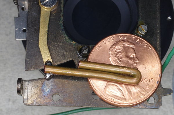 |
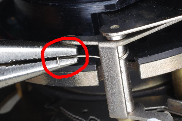
With the speed-lever rotated as far clockwise as possible,
carefully place the wire in the proper position as shown,
using a coin or somesuch to hold up the right end of the wire.
For both variants of the shutter, angle your wire slightly downward as shown
in order to keep the wire a bit farther from the conical cowl inside the body.
Once in position, touch the wire with a blob of molten solder on your iron until
the tin-solder melts. To avoid shifting the wire, don’t touch it with your iron.
|
 |
The prior photo was a variant 1 shutter.
If yours is variant 2 as in this photo, then the speed-lever is a little shorter,
and you’ll need to flip the wire over so the 15mm segment is *below* the 24mm segment
(instead of above it as in the prior photo). This is why I said to tin the other side
for variant 2.
Update: I discovered that you can also use this orientation for variant 1 shutters.
But don’t angle the wire.
|
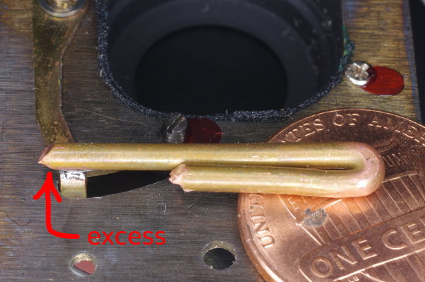 |
If you cut the wire a little longer than 25mm, you can place the excess to the left
of the speed-lever as shown.
In this example, 1.5mm excess was placed to the left of the lever as indicated by the red arrow.
|
 |
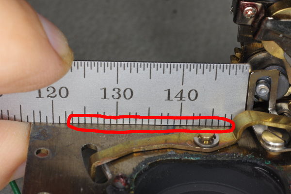
The soldering is done. This is a different camera than the prior photo, and this one
has no excess, as the wire is between 24-25mm long.
Push sideways on the wire to be certain the solder-joint is strong.
This is the low-speed position, and the bottom of the wire will rest on the floor of the casting.
You can see where I drew a mark for the floor along the bottom of the large shutter-plate.
The right end of the speed-lever is perfectly positioned.
|
 |
This is the high-speed position. Note the outward angling of the wire. Given how close
this wire got to the opening in the prior photo, I probably should have angled the wire
a little more.
|
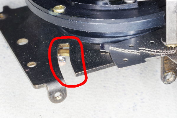 |
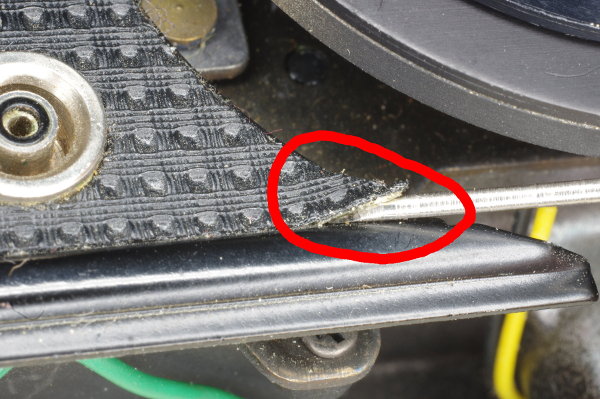
In the variant 1 design, the shutter-plate has a long slot located just below
the viewfinder, as shown in this photo. Light spilling down from the viewfinder can enter
this slot, where it can do no good.
|
 |
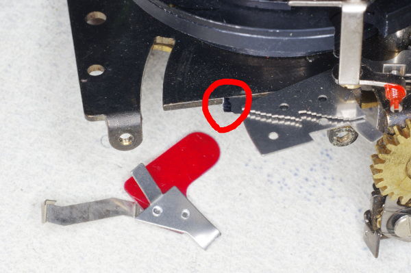
I suggest covering the slot with a piece of electrical tape.
But be sure to leave the hole exposed that is circled in red,
as a screw will go through it.
|
 |
The speed-lever was slightly stiff on one camera I modified because the other end of
the speed-lever pressed gently against the spring shown. Giving that the lever is
moved by gravity, even this slight friction can cause trouble.
|
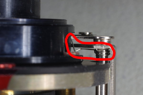
 |
Here’s an end-on view showing the lever touching the spring.
|
 |
The solution was to bend the lever upward slightly to avoid touching the spring.
I also twisted it counterclockwise as shown to ensure that it would block the lever
to its right as intended.
|
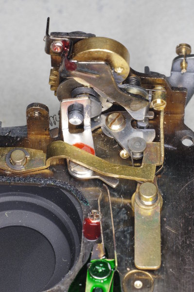 |
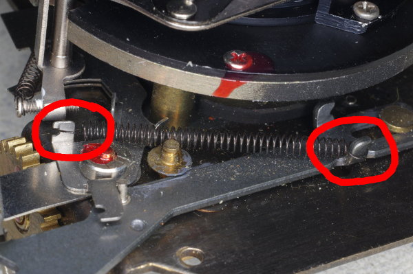
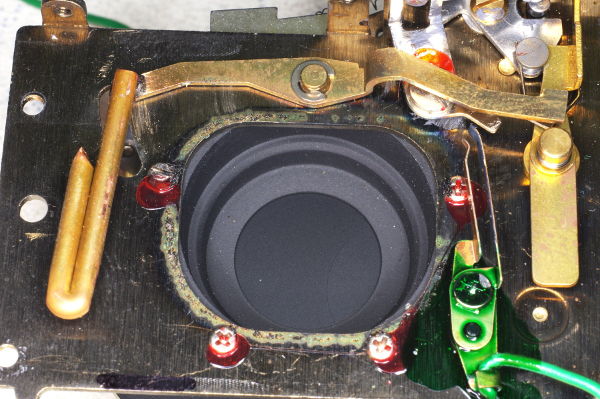
At this point, let’s see how the low/high speed selection works. This is the underside of
the shutter mechanism in its relaxed position.
|
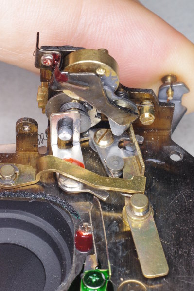 |
Here, the right-end of the long speed-lever is in the down position, which selects high speed.
I am pushing down on the shutter-release. Note that the long vertical brass lever on the right
has rotated counterclockwise a little (compare with the prior photo), which has rotated the
flywheel on top. Because the flywheel is now out of the way, the shutter blades will open and
close as quickly as possible (1/200 sec).
|
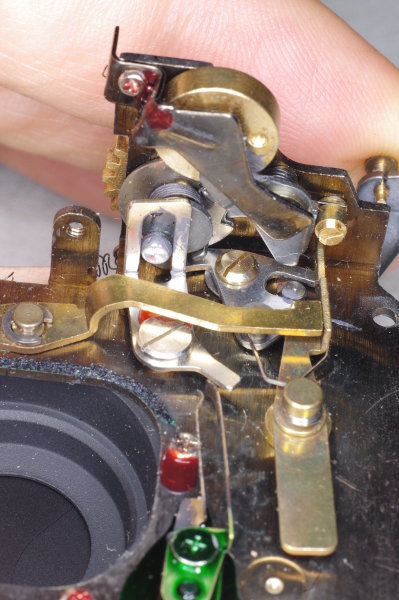 |
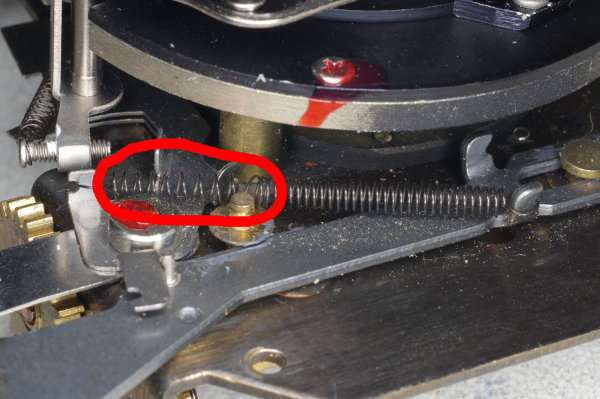
Now the right-end of the long speed-lever is in the up position, which selects low speed.
I am pushing down on the shutter-release. The right end of the speed-lever is preventing the
vertical lever from rotating, so the flywheel has not rotated. Therefore, the movement of the
blades will rotate the flywheel during exposure, slowing the speed down to 1/40 sec.
I suggest that you fire the shutter a few times in all orientations to ensure that your
manual speed modification is working properly. Remember, you cock the shutter by hand-turning
the gear on top by one revolution.
|
 |
You may now reassemble the camera by following the above steps in reverse order. The photos
that follow show some things to be aware of during reassembly.
This photo shows the shutter assembly fastened back onto the body. To avoid disturbing
light-sealing foam, try to place the shutter assembly straight down onto the body
in the correct position, with no side-to-side motion trying to find the correct position.
The viewfinder-assembly on a variant 2 camera is made out of plastic.
To avoid cracking the plastic, do not tighten its screws hard. You should consider locking
these (and other) screws with glue, paint, or Locktite.
|
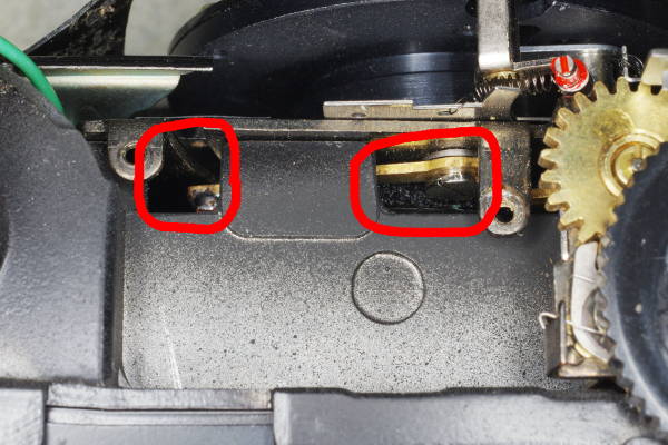 |
This top view shows two openings into the body’s interior. The viewfinder will occupy
this area (note the two threaded tabs), which means that sunlight can pass through the
viewfinder and into these openings, stressing the degraded light-seal foam that you saw earlier,
risking a light-leak.
I suggest blocking these openings as explained below.
|
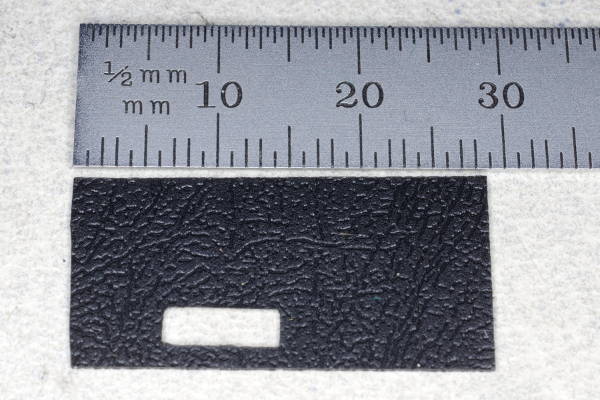 |
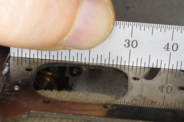
Cut some material that can block light into a length close to but not exceeding 30mm.
Pasteboard from product packaging will suffice.
In this photo, I used the back cover of a comb-bound manual.
|
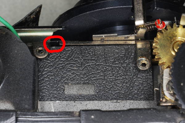 |
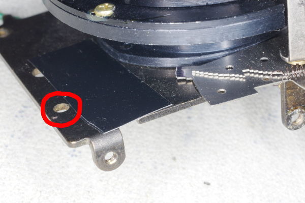
Place the material over the openings as shown, secured with a few dabs of contact cement.
But notice that a small hole still remains in this variant 1 shutter, circled in red.
|
 |
A small piece of electrical tape covers it.
|
 |
When you reattach the leatherette over the two panels you reinstalled, you will need
to use contact cement on older cameras. Newer cameras with double-sided tape are easier.
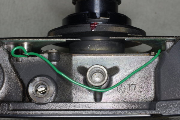
I like to preserve the original routing of the green sync-wire,
but I suppose this doesn’t matter.
|
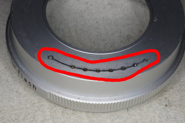 |
For smooth operation, smear a thin layer of grease over the detents on the f-stop ring.
|
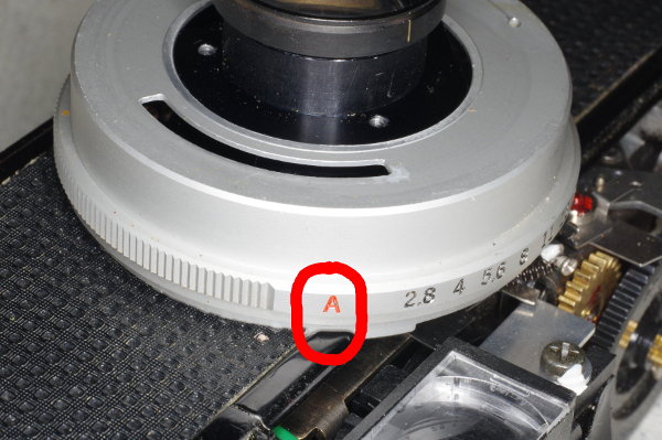 |
To ensure that the f-stop ring engages the f-stop pin correctly, place it on the body
with red “A” in the position shown.
|
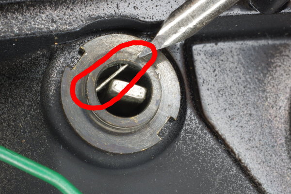 |
The rewind button will not go back in until you push this hairspring out of the way.
I suggest pushing it with a screwdriver as shown, but don’t push too far or it will
pop out and get lost.
|
 |
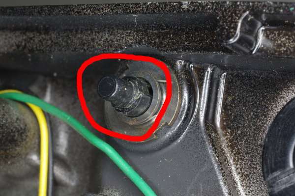
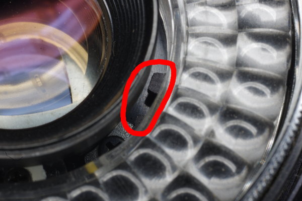
The inner focus-ring has a pin (circled in red) which mates with a claw on the body.
If these are misaligned, you won’t be able to focus.
|
 |
Here is the mating claw.
|
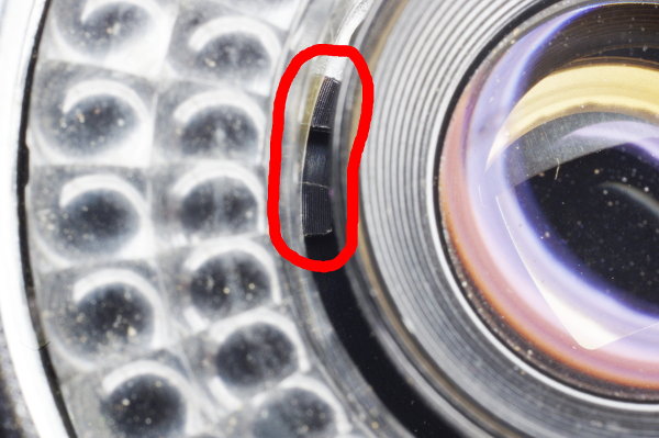 |
Here’s another view of the claw. Focus the lens at infinity by aligning the scratch with
the screwhead. Carefully place the ring on the lens without rotating the lens. I suggest
pressing a swab against the lens to block it as described earlier while manipulating the ring into place.
|
 |
After reinstalling the bottom plate, with the top cover still off, you can test the camera.
For example, you can check the focus-adjustment
by putting a ground glass on the back and examining it using a loupe with the shutter open.
But how do you keep the shutter open? If you jam a thin toothpick into the top mechanism
at the position shown, it will block the flywheel,
and the shutter will remain open until you withdraw the toothpick.
When reinstalling the top cover,
carefully route the flash-sync wire to avoid having it pass over the
front of the viewfinder (where it’s tallest), and to avoid being caught in other places.
The final (and optional) step is to replace the deteriorated foam light-seal
on the take-up side of the rear film door.
|
 |
Now go shoot some film!
|